


ELECTRICAL POWER SUPPLY
POWER SUPPLY — An adequate power supply and
proper wiring are important factors for maximum per-
formance and long life of the dryer. Electrical service
must be of adequate size to prevent low volt age dam-
age to motors and control circuits. All dryers should be
field provided with a dependable equipment ground.
Electrical power supply should conform to local, state,
or provincial requirements.
NOTE: The dryer's power supply wiring should enter
the PSC Box Assembly on the right-hand side of the
box.
POWER SUPPLY DISCONNECT — A power supply
disconnect switch external to the Control Box is rec-
ommended for all dryer installation sites. This discon-
nect switch is to permit total power shutdown before
opening ASC dead front, as required for inspection and
service and should be located close to the dryer for
quick shutdown.
TRANSFORMERS WIRING VOLTAGE DROP —
Contact the service representative of the power suppli-
er, to advise of the additional load to be placed on the
line. Check on KVA rating of transformers, consider ing
total horsepower load. The power supply wiring, main
switch equipment, and transformers must be capable
of providing adequate motor starting and operating
voltage. Voltage drop during motor starting should not
exceed 14% of normal voltage, and running voltage
(after motor is at full speed) should be within 8% of nor-
mal voltage.
ELECTRICAL LOAD — Table 2-2 indicates the electri-
cal load in horsepower and full load current, for motors
on the dryer.
OVERLOAD RELAYS — If for some reason a particu-
lar relay needs adjustment, most overload relays are
adjustable within a safe operating range of 85% to
115% of normal load in amperes by an adjustment
knob on the relay.
CONNECTING AUXILIARY CONVEYORS (OPTIONAL)
Auxiliary load and unload motor controls are not sup-
plied as a standard part of the dryer control panel. A
signal contact is provided to control a separate auxil-
iary load conveyor motor starter dedicated to this func-
tion.
A. All auxiliary equipment must be powered from a source
outside the dryer. Each auxiliary motor must have a
separate contactor and overload protection device.
B. For automatic operation: use 110V contactor coils and
connect auxiliary LOADING coil to terminal 128 of the
ASC terminal block and a neutral of the coil to the
power panel neutral. Connect auxiliary UNLOADING
contacts (N.O.) of the aux-unload contactor to termi-
nals 82 and 47 of the ASC terminal block. With this
setup, the dryer's unload auger will not run unless the
aux-unload contactor is energized. For automatic shut-
down of take-away when a burner lockout shut-down
occurs, connect 110V unloading coil to terminal 47 of
the ASC terminal block and a neutral point. Refer to
control circuit wiring schematics.
9
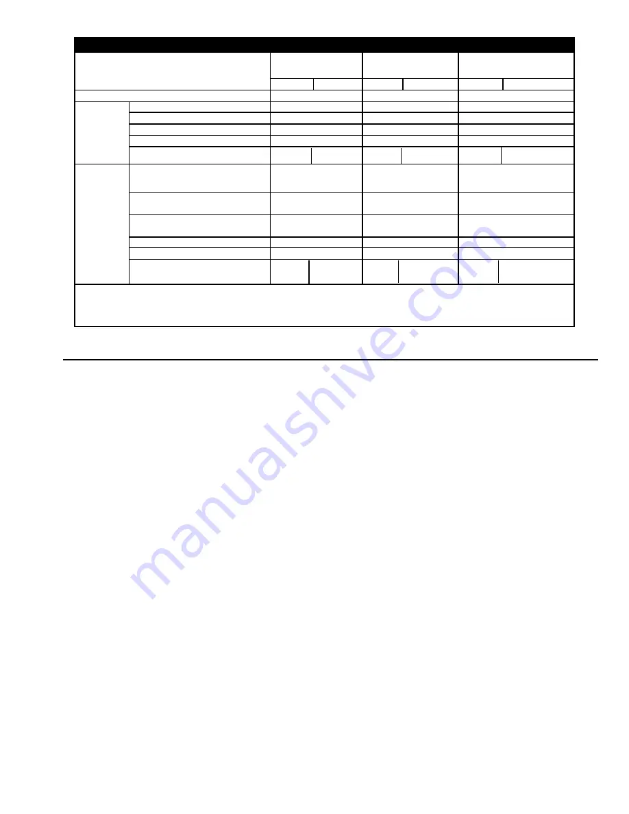
Liquid
Propane
(LP)
Natural
Gas
(N)
Total Max Fuel Flow - Gal./Hr.
1
Recommended Liquid Line Size
Heater Orifice Drill Size
Max. Burner Pressure (PSI)
Pressure Regulator Setting (PSI)
Total Max Fuel Flow
1
(1000 Cubic Ft./Hr.)
Minimum Pressure at
Connection to Dryer (PSI)
Recommended Minimum Line
Size - 100' Distance
Burner Orifice Size (dia.)
Max. Burner Pressure (PSI)
Regulated Supply Pressure to
Dryer (PSI)
C-2130B
C-2130B C-2130B1
7.0
76
1/2"
0.500"
7.0
4.0
8.0
7.0
8
2"
0.625"
5.5
3.5-10
7-10
1.
Maximum fuel flow rates listed assume full heat output for gas line sizing purposes. In normal operation the flow rates would
be considerably lower than indicated, due to actual setting used and cycling of heater.
2.
Uses stainless steel octagonal type burner.
Maximum Heat Capacity (Million BTU/hr)
T A B L E 2 - 1 F U E L S Y S T E M R E C O M M E N D A T I O N S
C-2140B
C-2140B C-2140B1
9.0
98
1/2"
0.500"
11.5
6.0
12.5
9.0
10
2"
0.625"
9.0
5-10
10
C-2160B, C-2175B, &
C-21100B
C-2160B
C-2160B1
12.0
130
3/4"
0.625"
9.0
5.0
10.0
12.0
10
2.5"
0.750"
7.0
5-10
10
Содержание C-21100B
Страница 22: ...20 ...
Страница 36: ...34 Fig 6 3 LP vaporizer assembly Fig 6 4 ASC control panel ...
Страница 49: ...Fig 8 1 Power circuit 220V 3 PH for C 2130B C 2140B C 2160B only 47 4B0280A TIF ...
Страница 50: ...48 Fig 8 2 Power cirucit 220V Part wind start for C 2175B C 21100 models only 4B0280C TIF ...
Страница 51: ...49 Fig 8 3 Power circuit 440V 3 PH for all C 2100B models 4B0280B TIF ...
Страница 52: ...Fig 8 4 Control circuit all models except part wind start p 1 of 3 50 4B0280D TIF ...
Страница 53: ...Fig 8 4 Control circuit all models except part wind start p 2 of 3 51 4B0280E TIF ...
Страница 55: ...Fig 8 5 Control circuit part wind start models only p 1 of 3 53 4B0280H TIF ...
Страница 56: ...Fig 8 5 Control circuit part wind start models only p 2 of 3 54 4B0280I TIF ...
Страница 58: ...Fig 8 6 Safety circuit portion of control circuit all models 56 4B0280G TIF ...
Страница 65: ......