background image

Aura 37


Technical specifications 


32 


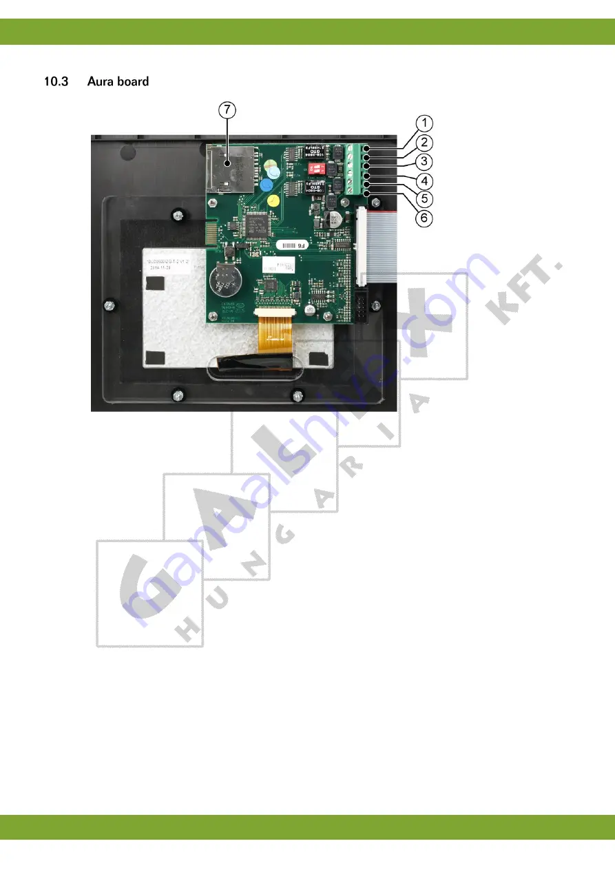
1.  IO Net - 

2.  IO Net + 

3.  Fnet 1- 

4.  Fnet 1+ 

5.  Fnet 2- 

6.  Fnet 2+ 

7.  SD Card 

Содержание AURA 37

Страница 1: ...g ...

Страница 2: ...oduced by Fancom For the latest information about product installation and operation please contact the customer service dept and or the technical service dept of the Fancom concerned In spite of the care taken when compiling this manual if you should discover any errors please inform Fancom B V in writing Fancom B V PO Box 7131 5980 AC Panningen the Netherlands Copyright 2017 Fancom B V Panningen...

Страница 3: ...5 Output status 12 5 Alarm 13 5 1 Alarm overview 13 5 2 Alarm settings 16 5 3 Alarm history 17 6 Installing the Aura 37 18 6 1 Determine location 18 6 2 Mount the Aura 37 18 6 3 Connect the Aura 37 19 6 4 Connect the Aura 37 to FNet 20 7 Installer settings 21 7 1 CFG 21 7 2 SYS 22 7 3 INF 23 7 4 IN 24 7 5 OUT 25 7 6 CMB 27 8 Appendix Connection diagram Aura 37 28 9 Appendix Connection diagram for ...

Страница 4: ...lowing symbols are used in this manual Tips and suggestions Note providing recommendations and additional information Warning indicating damage to the product if you do not follow procedures carefully Warning indicating danger to humans or animals Electrical shock hazard Danger to humans and animals Example of a practical application of the described functionality Calculation example Describes the...

Страница 5: ...rized installer Only replace a defective fuse by a fuse of the same type see connection diagram Inspect the control computer regularly for any damage Report any damage to your installer immediately A damaged control computer is dangerous Do not use running water high pressure cleaners to clean your control computer The control computer is water resistant but not waterproof Do not switch off the co...

Страница 6: ...ontrol using analog output Ventilation sidewall and tunnel inlet using analog output Ventilation settings in Ventilation linear or modulation control Ventilation by adding eight additional fan outputs Temperature measurement for two house sensors Temperature measurement for outside sensor Relative humidity measurement Curve settings on day number for set temperature set relative humidity min vent ...

Страница 7: ...describes the main parts and the operation of the Aura 37 The Aura 37 can be operated on the touch screen 1 Touch screen The controller is automatically activated as soon as you switch on the power The start up progress is shown on the screen ...

Страница 8: ...e used to switch between user and installer views 2 Working area Displays the data of user or installation settings of the control computer 3 Menu selection and alarm bar Provides buttons to navigate through available menus e g curve and an alarm indicator to navigate to more details In the Aura 37 the Setpoint house temperature and Start ventilation temperature are equal In this manual both are u...

Страница 9: ...zone 2 Actual measured temperature 3 Actual measured temperature 4 Upper boundary of the comfort zone Ventilation dial 1 Minimum ventilation 2 Actual calculated ventilation 3 Calculated ventilation 4 Maximum ventilation Humidity dial 1 Minimum relative humidity 2 Actual measured relative humidity 3 Actual measured relative humidity 4 Maximum relative humidity Readout of the heating status Yellow O...

Страница 10: ...up of the dial appears 2 Set the value by tapping Tap to increase or decrease the value step by step Hold the to quickly increase or decrease the value 3 Tap to confirm or to cancel all the settings in the popup window The temperature control ensures it does not become too cold in the section If the temperature drops below the set value the computer will make a correction Dial Setting the setpoint...

Страница 11: ...ling Setpoint heating and Setpoint cooling can be linked to the Setpoint house temperature The ventilation control ensures there is always a settable minimum amount of fresh air If the temperature in the house becomes too high the controller will provide extra ventilation Dial Setting of the minimum ventilation Setting of the maximum ventilation ...

Страница 12: ...ing of the relative humidty setpoint It is possible to set the curve for temperature relative humidity and ventilation There are 10 bending points At a bending point start by entering the day number the settings at this bending point apply to this day number Readout of the actual control values setpoints Setting to adjust the offset between setpoint and curve value Readout of calculated curve valu...

Страница 13: ...ntilation The day number is a counter increased by the controller each day at midnight by one up to a maximum of 999 If the day number is 0 it will not change The Aura 37 then controls without the curve even if the bending points have been set If a curve is used the day number is the basis used to calculate the setpoints from the relevant curve If a negative day number is set the Aura 37 will cont...

Страница 14: ... lowest measured temperatures of outside temperature sensor Followed by the time of measurement Readout of the highest actual and lowest measured temperatures of relative humidity Followed by the time of measurement The highest and lowest values are measured over the last 24 hours Registration of water feed and auxiliary inputs representing the today yesterday day before yesterday values and the t...

Страница 15: ...on of the fans and the temperature on which the fan is currently controlled Readout of the ventilation status 8 combi fans Blue ON Grey OFF Readout of the heating status Yellow ON Grey OFF and the temperature on which the heating is currently controlled Readout of the cooling status Blue ON Grey OFF and the temperature on which the cooling is currently controlled Readout of the relative humidity s...

Страница 16: ...et the status will be changed to Alarm stand by Alarm recovered there was an alarm which has been recovered The controller switches off the alarm but the alarm status remains visible Silent alarm alarm message shown on screen only Alarm temp off switch off the current alarm When the alarm situation has been cancelled this status will automatically become Alarm stand by Always check that the status...

Страница 17: ...ackup alarm The control computer will be active on factory settings Please check the settings Watchdog alarm Communication alarm Setting changed Stack overflow Communication assignment EPROM error System error Protected software The control computer also tests a number of functions of the control computer itself Always warn the installer if a system alarm occurs Power failure When the control is p...

Страница 18: ...e alarm situation 3 Press once more The alarm message will disappear and the alarm status changes into Alarm temp off followed by Alarm stand by If the alarm is disabled the control computer will not generate any alarm messages except system alarms Never switch the alarm off during regular operation The alarm can be fully disabled e g when the house is empty Disable the alarm as follows 1 Press 2 ...

Страница 19: ...eratures the maximum alarm limit would then be unnecessarily high In order to provide effective alarms dif maximum alarm as small as possible the computer increases the alarm limit parallel to the outside temperature as soon as this is higher than the point at which ventilation is maximum Calculated end temperature ventilation 24ºC Outside temperature 25ºC Max difference alarm 3ºC Calculated alarm...

Страница 20: ...e becomes lower than 16ºC Temperature sensor failure Measurements from connected sensors except the outside sensor are reliable as long as measurements are between 9 9ºC and 99 9ºC Outside these limits the measurements are unreliable The control computer will give an alarm This can mean that the temperature sensor has not been correctly connected or is defective The screen displays at the temperat...

Страница 21: ... Aura 37 near water pipes drainage pipes etc Never mount the Aura 37 in a humid and or dusty room and certainly not in the room where the animals are present Mount the Aura 37 at such a height that you can control the Aura 37 easily eye level and square on a solid backing The swivels should be positioned at the bottom Mount the Aura 37 as follows 1 Mark the screw holes by using the drilling templa...

Страница 22: ... of moisture dust and or aggressive gasses Check that the mains voltage and frequency for which this computer is suitable correspond to the mains voltage and frequency on site Be sure that the Aura 37 is properly grounded When using metal cable trays grounding at one point of the tray is recommended The Aura 37 should be possible to shut down with a double pole switch Connect the Aura 37 to a grou...

Страница 23: ... a dipswitch is used to terminate the control computer Example Setting the terminal resistor FNet Four control computers connected using FNet Control computers 1 and 4 are at the end of the network These control computers must be terminated Control computers 2 and 3 are looped These looped control computers do not require a terminal resistor The Fancom Greenlink cable UTP 1x2x0 8mm unshielded twis...

Страница 24: ... the type version and build number of this computer Computer number FNET Setting of the unique computer number If the computer is part of Fnet communication it must have its own unique number like all the other connected computers To avoid peak load on the net by several computers activating simultaneously Fancom advises always entering a computer number Computer name Setting of the computer name ...

Страница 25: ...the control computer is included in a network only one control computer in the network must be set as MASTER Set all the other control computers as SLAVE Sent receive counter Readout the number of transmitted messages Sent counter and readout of the number of received messages Receive counter no PC messages These counters can be used to trace faulty communication connections In this case set all t...

Страница 26: ...een the Start temperature ventilation and End temperature ventilation C Influence calculation Readout of the actual calculated influence C Influence factor 1 5 Influence maximum 4 0 C The maximum difference between Start temperature ventilation and End temperature ventilation is 1 5 x 4 0 6 0 C Influence high relative humidity on the minimum ventilation On minimum ventilation Setting if the high r...

Страница 27: ...ng of the relative humidity percentage above which the evaporative cooling stops 0 to 100 Temperature sensor 1 temperature sensor 2 temperature sensor outside Input type Setting indicating the analog control type NONE SENSOR EXTERNAL External only used for temperature sensor outside Input number analog Readout of the sensor input number Correction Setting of the difference offset in the measured t...

Страница 28: ...ntrol only settable if no tunnel inlet is used Exhaust fan Sidewall inlet Tunnel inlet NONE 10 0V control 0 10V control Modulating 10 0V control Modulating 0 10V control Tunnel inlet is only settable if no heating 2 is used Cooling Humidification NONE ON OFF Modulating Output number analog relay Readout of the output number Sensor selection Setting on which temperature sensor the control output wi...

Страница 29: ...t to the output Correction buffer Setting of the correction buffer by using other control types Correction buffer Each control time the computer registers the difference between the measured and control value and adds this to any previous differences As soon as the total sum exceeds the value of the correction buffer the computer will correct the output Sidewall inlet tunnel inlet Pre run time sec...

Страница 30: ...ng of the required exhaust positions 12345678 Setting the relais 0 fan off 1 fan on M modulating fan only possible if modulating fans are used and is not selectable in tunnel Side Setting the side wall inlet position Tun Setting of the required tunnel inlet position Modulating fans is possible when the Exhaust fan output is set to None OUT menu In the CMB menu the text Exh will be replaced by Mod ...

Страница 31: ...Aura 37 Appendix Connection diagram Aura 37 28 ...

Страница 32: ...Aura 37 Appendix Connection diagram for alarm 29 ...

Страница 33: ...12 Vdc Low level 1 5 V Frequency 0 10 Hz 13 relay outputs Relay 4 voltage free Max 2A 60Vdc 30Vac Relay 1 8 voltage free Max 2A max 240Vac Alarm relay voltage free Max 2A 60Vdc 30Vac 3 analog outputs Voltage range 0 10Vdc Maximum load 1mA Output resistance 570Ω Housing Plastic housing with screw on lid IP54 Dimensions l x w x h 300x240x140mm Weight unpacked 3 0kg Ambient climate Operating temperat...

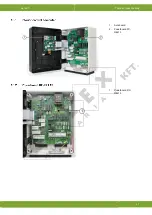
Страница 34: ...Aura 37 Technical specifications 31 1 Aura board 2 Powerboard FC REL13 1 Powerboard RC REL13 ...

Страница 35: ...Aura 37 Technical specifications 32 1 IO Net 2 IO Net 3 Fnet 1 4 Fnet 1 5 Fnet 2 6 Fnet 2 7 SD Card ...

Страница 36: ...Place Panningen the Netherlands Hereby declares that Aura 37 Satisfies the conditions of 1 The Low Voltage Directive 2014 35 EU according to EN 61010 2 the EMC Guideline directive 2014 30 EU Emission and immunity according to NEN EN IEC 61326 Place Panningen Date 04 1 2018 Paul Smits Managing Director ...

Отзывы: