background image


1.5Safety instructions in transport, storage and installation 

(1)The equipment must be placed and handled by professionals. 

(2)Please use designated tools (steel cable, crane, hoist etc.) to lift the 

equipment according to designated sequence and method. 

(3) Authorized staff only for lift operation. 

(4) In order to prevent serious injury accidents, no one is allowed to be under 

the equipment during hoisting. 

(5)The capacity of hoisting tools should be more than total weight of the 

equipment. 

(6) When the equipment is stored temporarily, please place the equipment at 

level and keep a constant temperature and indoors clean. 

(7) For transportation, it is not allowed to damage the equipment by packing. It 

should be reported to the manager immediately in case of any machine 

damage and missing parts during transportation. 

(8) In installation, enough clearances should be allowed for future maintenance 

and replacement of the equipment. 

(9) Prior to installation, all machine parts must be kept in their original package. 

The machine parts and packing boxes should be properly covered and stored 

in places sheltered from rain, sunlight and damp. 

(10)The cover plate, protection hood or guard grating are usually installed and 

delivered together with the machine. They can only be disassembled with tools. 

And the machines required with the operation devices can never put into work 

until such devices have been properly installed. 

1.6 Safety instructions in operation, inspection and maintenance 

(1) The operation, inspection, repair and maintenance of the equipment shall be 

carried out only by the trained technical personnel according to 

Содержание Muyang SZLH Series

Страница 1: ...Muyang SZLH Series Belt Pellet Mill Concise and practical manual This book is for operation and maintenance only It does not have any legal effect For details please refer to the product instructions ...

Страница 2: ...zard 11 1 9 Other safety precautions environmental protection measurements 13 2 General Description 1 2 1Application and adaptability 1 2 2Main features and functions 1 2 3Main structureand working principle 2 3 Specification of the pellet mill 1 3 1 Working condition 1 3 2Meanings of the model 2 3 3Accessory equipments 2 3 3 1Feeder 2 3 3 2Conditioner 3 3 3 3 Steam system 3 4Transportation instal...

Страница 3: ...1Instructions for inspection repair and maintenance 18 6 2 Cleaning 19 6 3 Lubrication 19 6 3 1Selection of lubricant grease 19 6 3 3 List of daily inspection items prior to each running or each running 20 6 3 4 List of regular inspection items 21 6 4Tools for repair and maintenance 21 6 5 Malfuntion and troubleshooting 22 6 6 Spare parts 25 6 6 1Spare parts 26 6 6 2Ordering list of spare parts 27...

Страница 4: ...pressure 0 6Mpa 3 To facilitate use operation and maintenance and inspection of the machine adequateclearances around it shall be required 4 Please place the equipment horizontally 5 The vibration by other complicated environmental conditions may not exceed12 mm s 1 1 2Description of warning signs 1 In order to well understand this operation Manual the safety warning signs are divided into followi...

Страница 5: ...e this equipment according to relevant stipulations of safety instructions 1 3Description of safety signs 1 Relevant safety signs are posted at the corresponding dangerous positions of this equipment to personal safety 2 Please well understanding the safety signs 3 Please place these safety signs near the equipment 4 When these safety signs have fallen off or been damaged please replace them with ...

Страница 6: ... is running and until it has not been completely stopped Beware of scalding Do not touch the machine with bare hands when it is normally working Do not remove the guard shield when the machine is running Protective gloves must be wornwhen inspecting and repairing the equipment ...

Страница 7: ... Do not climb or stand on the equipment For the position where the above mentioned safety signs are attached refer to the following figure ...

Страница 8: ...ilities for any accidents or damage to the equipment shall not be borne by manufacture and commission agent if the equipment is not operated according to the Operation manual 7 Please install use and operate the equipment correctly Whoever taking off of guard or signs to destroy its function should be responsible for the safety consequences 8 Any changes to the equipment shall not affect the funct...

Страница 9: ...rted to the manager immediately in case of any machine damage and missing parts during transportation 8 In installation enough clearances should be allowed for future maintenance and replacement of the equipment 9 Prior to installation all machine parts must be kept in their original package The machine parts and packing boxes should be properly covered and stored in places sheltered from rain sun...

Страница 10: ...ction device and operating gate are open It is prohibited to open the operating gate until the machine comes to full stop 6 If any trouble occurs in the operating gate and safety protection device please repair or replace them at once 7 The safety protection devices can never be dismounted covered or bypassed at liberty It can never be opened until the machine has completely stopped And the machin...

Страница 11: ...ase repair or replace them immediately 15 Ensure the safety of the electric system Before the electric circuit is cut off it is strictly prohibited to open the junction box to avoid electric shock 16 The electric control system of the pellet mill must comply with the following instructions Otherwise the technical safety responsibility of the supplier will be denied The electric control system of t...

Страница 12: ...ions to ensureoperators safety The coupling shield should be amounted at any time and kept in place It is very dangerous when they are opened or dismantled It may cause casualty accident This is also applicable to the preventive device of the robot The safety limit switches should always be kept in good order Bypass or discard of the safety limit switches is not allowed The drive motor must be swi...

Страница 13: ... exception the power supply of motors must be cut off completely and the switch must be locked out with warning tag attached Attention must be paid to safety measures for climbing Be careful sampling from inside of the machine can never be carried out unless there is not any danger Usually the samples can be taken from the pipe under themachine instead of inside of machine Clean out the deposited ...

Страница 14: ...ently and effectively everywhere Keep all motors free of deposited dusts 2 Regular inspection and maintenance Check the safety devices such as speed monitor or the like apparatus regularly at least once a week Check and clean magnetic separators at least once a day In order to avoid heat generation it is necessary to regularly check the functions of all main shafts and bearings at least once a wee...

Страница 15: ...on should be installed on power line according to local regulation b Check whether the operating voltage and frequency are in line with the data displayed on the machine nameplate and control cabinet c All power lines of control system should be connected as per schematic diagram to hook up withcorrect switch phase line of a single phase source 4 Smoking and welding Smoking is forbidden which is a...

Страница 16: ...veyor If the welding work is required shut down the machine first and then make a thorough cleaning and isolate both sides of the welding site tightly with materials like mineral wool to avoid connecting with other conveying devices silos or tanks If the work is to be done on the chutes or conveying pipes it is necessary to disassemble them or disconnect their lower ends with silo or tank and seal...

Страница 17: ...ine like motor oil gearbox oil brake oil and coolant etc into special containers and send them to the designated workshop 2 The plastic parts shall be picked up for reutilization 3 The metal parts shall be sorted out for special handling ...

Страница 18: ...ordering 2 2Main features and functions 1 Double motor V belt and synchronous cog belt timing belt step driving system is employed for this machine which is characterized by ideal drive ratio great driving moment smooth rotation simple structure small space occupation high output low noise and easy operation maintenance 2 SZLH550 170 Pellet Mill is configured with three or two press rollers and ea...

Страница 19: ...m and hydraulic system optional for SZLH550x170 etc The working procedure is shown as follows Mixed mash of a moisture content below 18 is from mash bin to feeding screw before entering the conditioner at a proper flow rate by adjusting the frequency inverter to control motor rotating speed The material will be sufficiently mixed with steam by the mixing effect of stirring paddles in the condition...

Страница 20: ... Air supply for normal use 0 4Mpa Voltage for normal use AC380V Note if the actual condition fails to comply with the environment condition No the temperature shall be adjusted properly If it fails to comply with condition No please refer to the motor specifications to customize the gear motor 3 Configuration conditions The Pellet Mill should match the equipment upstream and downstream in process ...

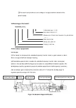
Страница 21: ...cy converter to output different rotation speeds For detail please see the operation manuals of variable speed motor and frequency converter 3 A cycloid pin gear reducer with a reduction ratio of 1 17 allows the feeding auger to regulate speed in a range of 0 54 r min Fig 3 1 Schematic diagram of feeder SZLH550 170 Effective size of the die inner diameter of ring die effective width mm Model ring ...

Страница 22: ... material 3 The conditioner serves the function of introducing steam at a certain pressure and a proper amount of oil and or molasses through the liquid inlet as required tocondition the compound mash to a certain temperature and moisture so as to improve the feed value and pelletizing performance of the feedstuffs Fig 3 2 Schematic diagram of conditioner 3 3 3 Steam system Bearing Housing and mai...

Страница 23: ...ider about the actual condition on job site The pressure reducing valve should be installed about 4 5m 6m away from the steam inlet of conditioner while the regulating valve should be installed 0 2m 2m away from the steam inlet of the conditioner The minimum distance between the steam manifold and the conditioner should be 10m Table 3 1 is a reference of the specification and amount of valves and ...

Страница 24: ...ge and Accessories 2 1 6Mpa 1 6Mpa 1 6Mpa 1 6Mpa 1 6Mpa Remark s 1 The draining pipeline and 3 4 reducing valve can be connected by threads and others shall be connected by flanges 2 The pressure reducing valve shall be installed 4500mm away from steam inlet of the conditioner 3 Steam consumption of the pellet mill shall be calculated based on 50 Kg steam per ton of granular material 4 Pressure re...

Страница 25: ...isted equipment see Table4 1 and not too short The angle between every two cables is not necessarily equal to 60 Actually an angle less than 60 is better but it requires a much longer rope The bearing capacity of the hoisting equipment shall be 1 2 times larger than the weight of the equipment to be hoisted Fig 4 1 Hoisting diagram Table4 1 Accessory equipment and parts weight parameters of SZLH55...

Страница 26: ...ented against collision and overturn of the equipment If a packing case is used the complete machine and accessories shall be fixed securely in the case and a certain clearance shall be reserved from the boards of the packing case so as to avoid collision and damage in transport During transport any overturn heavy loads or collision are not allowed onto the machine body 2 Storage If the machine eq...

Страница 27: ...ize pellet mill running The installation area shall be level and rigid The machine base shall not only connect to the frame structure by bolts but also with the anchor bolts Otherwise it will cause the vibration of machine or even accidents d If the pellet mill is not installed at the operation elevation a working platform is requiredto facilitate the operation and maintenance e There shall be eno...

Страница 28: ...ic lubrication device Compressed air with a pressure above 0 4Mpa should be provided 4 2 3Installation of steam pipeline Refer to Section 3 3 3 Steam system for the installation process flow of steam pipelines and type selection of pipe fittings Note 1 The steam pipeline should be installed by professional installation company according to local laws and regulations 2 Abide by rules and regulation...

Страница 29: ...the right side of pellet mill preferred and about 0 5m 3m away from the machine or 1 0m 3m away at the left side of the machine The motors shall be interlocked during installation of power cables The connection sequence is as following 1 Hydraulic motor if it is selected 2 Main motors of principal machine 3 Motor of the conditioner 4 Motor of the feeder There shall be a release device for the main...

Страница 30: ...justment pay attention to the adjustment of the clearance between the press rollers and the ring die 4 Fill up lubricants according to the lubrication diagram 5 Look at the oil level in oil box of hydraulic system if normal if a hydraulic system is in place 6 Start the hydraulic pump motor and check the manometer for proper pressure value On the first day of operation these rated values should be ...

Страница 31: ...ntil pelletsare formed This is for primary lubrication of the ring die before normal production 4 Start the conditioner motor 5 Start the feeder motor adjust the frequency converter to a low frequency and allow the feed to enter the conditioner slowly and then the pelletizing chamber Do not add any steam at the beginning of pelletizing and slowly accelerate the feeding based on the current of the ...

Страница 32: ... is out of the ring die then stop the main motors 3 If the machine is out of service for a while at the end of a working day as an example use oily mash material to manually feed the inlet till the oily pelletsareformed This will facilitate the start of ring die next time when the Pellet Mill resumes working 4 Shut down two main motors when the oily pellets fill up all the die holes 5 Switch off h...

Страница 33: ... or on the control panel of the equipment Prior to maintenance use this safety switch to stop the equipment For maintenance the protective gloves maximum temperature up to 100 safety shoes with steel toe and safety hat should be worn 1 Personnel safety protective device Fig 5 2 Pellet mill door is equipped with a limit switch1 When pellet mill door is closed the contact terminal of limit switch is...

Страница 34: ...shatfwhile the ring die is on the rotor When the rotation torque of the main shaft reaches a certain design value the shear force transferred to the safety pin 1 installed on the rear end of the main shaft exceeds the limit of the safety pin thus the safety pin is sheared off At this time the main shaft is rotating making the limit switch 2 activated thus stopping the motors of pellet mill Note Be...

Страница 35: ...he machine will resume normal running Fig 5 5Emergency discharging device 4 Safety speed sensor A safety speed sensor is amounted nearby the belt pulley of countershaft to sense the rotation speed A speed sensor instrument is available on the control panel to display the rotation speed of the countershaft belt pulley which can set the minimum rotation speed for the belt pulley When the pellet mill...

Страница 36: ...een discharge outlet of conditioner and inlet of pellet mill gate can remove the trap iron mixed in materials efficiently and protect the ring die and press rollers from damage Fig 5 6 Magnetic separating device Magnet ...

Страница 37: ...ting hood guard grating etc are installed and in good order functionally 6 When in need to open the safety guards or access doors or to take the safety devices off for inspection adjustment repairing maintenance and parts replacement pleaseset up required safety procedures and work out safety action plans prior to such operations 7 Be sure that the above said safety devices and guards areput back ...

Страница 38: ...eposited here weekly Hydraulic device Thoroughly clean the hydraulic system with jet air blowing every week Pellet mill body front part fasteners of ring die rotor the place where the flange enters Clean out dirt materials or fat deposited into the chamber on monthly basis Pellet mill body middle part access to the timing belt Clean once every six months Interior of conditioner and feeder Open che...

Страница 39: ...0 6Mpa Everyday Inspection Adjust the air pressure 4 Bearing Check for temperature lower than45 Everyday Thermometer Checking 5 Motor Check for temperature lower than45 Everyday Thermometer Checking Check whether the current value is in rated range Everyday Ammeter Checking Check for the level of lubricant grease and if abnormal noise Everyday Inspection Checking 6 Temperature sensor Check for nor...

Страница 40: ...ure 6 Safety device Check on warning signs for missing or wear out Every month Inspection Replacing Safety switch safety pin Every month Cleaning replacing Note1 Assuming the duty cycle as 12h a day and 25 days a month Customers can make adjustment according to actual conditions 6 4Tools for repair and maintenance No Tool name Spec Function 1 Screwdriver Tightening bolts 2 Ammeter Measuring the cu...

Страница 41: ...rouble Cause Solution 1 Feed cannot enter the ring die 1 Feeding inlet is clogged 2 The conditioner is plugged up 3 Feeder drive doesn t work 1 Clean the feeding inlet 2 Clean the conditioner 3 Check the driving device of feeder 2 Material can enter the ring die but cannot be pelletized 1 The press rollers and ring die are worn out 2 Too many die holes are clogged 3 The feed formula is changed 4 T...

Страница 42: ... 4 The limit switch is tripped due to rotation of pellet mill main shaft by overload or material jam between press roller and ring die 5 Insufficient pressure from anchor ear or oil on brake disc causing slippagereleasing the main shaft to rotate and the limit switch released 6 Circuit broken down 1 Readjust the tension of V belt or check the pressure reading on the pressure gauge of hydraulic sys...

Страница 43: ...of V belt in a group varies 3 V belt is contaminated by grease 4 Wrong location of V belt 5 The shape of V belt is incorrect 1 Tighten the V belt as required 2 Replace with a group of belt in the same size 3 Clean the V belt and pulley 4 Correct the motor and middle pulleys 5 Use qualified V belts 10 Capacity of the pellet mill is not enough with main motor at full load 1 Too much steam only for m...

Страница 44: ...is insufficient 5 Bad bearing end cover and seal ring are used 6 Unqualified press roller bearings provided by other manufacturers 1 Improve cleaning of material 2 Adjust the clearance between the press roller and ring die 3 Apply lubricant grease as specifies Section 7 2 1 4 Apply enough lubricant grease as specified Section 7 2 2 5 Replace the end cover of bearing and seal ring with correct ones...

Страница 45: ...accidents should occur accordingly Therefore these parts and components shall be replaced in timely fashion after a certain period The spare parts in this Operation Manual are also called wearing parts Timely and accurately ordering of spare parts will inspire your production So in order to purchase correct spare parts when placing an order please indicate the corresponding serial number code desc...

Страница 46: ...6 6 2Ordering list of spare parts Model ofpellet mill Power Series No No Part code Muyang code Part name Qty Remarks Note This list can be copied or made into electronic form ...

Отзывы: