23
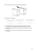
6.5.5 Run a bead of silicon 5mm from profile edge as highlighted below.
6.5.6
Slide suited units into position
.
6.5.7 (A) Right hand unit: Screw the M5 x 40 screw (supplied in the kit) into one of the
suiting plates as shown and then insert through the front fixing holes of both units.
6.5.8 (B) Left hand unit: Slide the penny and lock washer on to the screw and secure using
the M5 nut.
6.5.9 (C) Remove the front bolts from feet, insert base tie plate and secure the bolts back
into position.
Содержание E9460
Страница 18: ...18 6 0 INSTALLATION ELECTRICAL SAFETY AND ADVICE REGARDING SUPPLEMENTARY ELECTRICAL PROTECTION...
Страница 24: ...24 6 5 10 D Replace fixings on the rear hob and tighten screw caps into position 6 5 11 Replace control panel...
Страница 31: ...31 7 7 CIRCUIT DIAGRAMS 7 7 1 E9490 Circuit Diagram...
Страница 32: ...32 7 7 2 E9460 Circuit Diagram...
Страница 33: ...33 7 8 WIRING DIAGRAMS 7 8 1 E9490 Wiring Diagram...
Страница 34: ...34 7 8 2 E9460 Wiring Diagram...

