background image


Falcon Foodservice Equipment


HEAD OFFICE 


Wallace View, Hillfoots Road, Stirling. FK9 5PY. Scotland.


WEEE Directive Registration No. WEEE/DC0059TT/PRO


At end of appliance life, dispose of appliance and any replacement parts in a 
safe manner, via a licensed waste handler. Appliances are designed to be 
dismantled easily and recycling of all material is encouraged whenever 
practicable.


Dear Customer 
 
Thank you for choosing Falcon Foodservice Equipment.  
 
This  manual  can  be  downloaded  from 

www.falconfoodservice.com


or  scan 

here: 


IMPORTANT: 

Please keep this manual for future reference. 

Содержание E9460

Страница 1: ...User installation and servicing instructions ELECTRIC CHARGRILL E9460 E9490 Read these instructions before use T100896 Rev No 3 Published 23 05 2019 DATE PURCHASED MODEL NUMBER SERIAL NUMBER DEALER SE...

Страница 2: ...iance and any replacement parts in a safe manner via a licensed waste handler Appliances are designed to be dismantled easily and recycling of all material is encouraged whenever practicable Dear Cust...

Страница 3: ...3 SYMBOLS SCREWDRIVER SPANNER COOKING OIL GREASE WARNING SPARK IGNITION FLAME VIEWPORT ALLEN KEY IGNITER C SPANNER REMOVE DEVICE PLUG REMOVER...

Страница 4: ...ssional use only and must be used by qualified persons The installer must instruct the responsible person s of the correct operation and maintenance of the appliance Unless otherwise stated parts whic...

Страница 5: ...health and safety of your business you must control any risks identified in your commercial kitchen To do this you need to think about what might cause harm to people and decide whether you are taking...

Страница 6: ...5 0 DIMENSIONS CONNECTION LOCATIONS 17 6 0 INSTALLATION 18 6 1 SITING CLEARANCES 19 6 2 ASSEMBLY 20 6 3 ELECTRIC SUPPLY CONNECTION 20 6 4 COMMISSIONING 21 6 5 SUITING 22 7 0 SERVICING 25 7 1 ACCESS P...

Страница 7: ...elevant EU directives for the heat inputs gas pressures and voltages stated on the data plate A Serial No B Model No C Flue Type D Gas Category E Gas Pressure F Gas Type G Gas Rate H Total Heat Input...

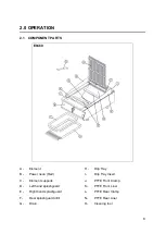
Страница 8: ...ement H Drip Tray B Power neon Red I Drip Tray Insert C Element supports J PTFE Front Clamp D Left hand splashguard K PTFE Front Liner E Right hand splashguard L PTFE Rear Clamp F Rear splashguard inf...

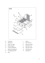
Страница 9: ...Element J Drip Tray Insert C Power neon Red K PTFE Front Clamp D Element supports L PTFE Front Liner E Left hand splashguard N PTFE Rear Clamp F Right hand splashguard O PTFE Rear Liner G Rear splash...

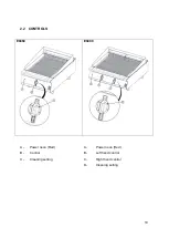
Страница 10: ...10 2 2 CONTROLS E9460 E9490 A Power neon Red A Power neon Red B Control B Left hand control C Cleaning setting C Right hand control D Cleaning setting...

Страница 11: ...ING TO MAINTAIN ELEMENT HEAT TURN THE CONTROL TO A LOWER SETTING 2 4 CHEF S RECOMMENDATIONS 2 4 1 Element temperature must be regulated for different circumstances 2 4 2 The food absorbs heat from the...

Страница 12: ...hot oil for example are an explosive mix and should be avoided at all costs Other useful references for health and safety issues www hse gov uk Essentials of health and safety at work ISBN978 Noise a...

Страница 13: ...hould carbonize and fall off the elements 3 1 4 Scrape off any remaining debris using the element cleaning tool provided 3 1 5 When cold the elements may also be cleaned using a cloth and hot soapy wa...

Страница 14: ...e splash guard is removable for cleaning 3 1 10 The front and rear element support bars are also removable for cleaning 3 1 11 To lower elements disengage locking pin and lower as required DO NOT USE...

Страница 15: ...ar PTFE Clamps and old PTFE Liner 3 2 2 Lift the elements to the vertical position and engage locking pin 3 2 3 Fit front rear liners into appliance and fold PTFE to match the profile of the hob and p...

Страница 16: ...HT kg PACKED WEIGHT kg E9460 49 62 E9490 60 77 4 2 TECHNICAL DATA TABLE E9460 CURRENT POWER PHASE MIN A 230V MAX A 230V ACTUAL A 230V kW 230V L1 10 00 11 67 11 11 3 36 L2 13 09 15 28 14 55 3 36 L3 10...

Страница 17: ...17 L3 20 00 23 33 22 22 3 36 IF ANY CURRENT IS OUT WITH THESE TOLERANCES THE CAUSE MUST BE INVESTIGATED AND RECTIFIED 5 0 DIMENSIONS CONNECTION LOCATIONS...

Страница 18: ...18 6 0 INSTALLATION ELECTRICAL SAFETY AND ADVICE REGARDING SUPPLEMENTARY ELECTRICAL PROTECTION...

Страница 19: ...allation and connections should meet the necessary requirements to the local electrical wiring regulations and any electrical safety guidelines We recommend Supplementary electrical protection with th...

Страница 20: ...ection 5 0 This unit is suitable for AC supplies only The standard terminal arrangement is Three phase 400V 3N for all variants Live 1 Phase 1 Brown Live 2 Phase 2 Black Live 3 Phase 3 Grey Neutral Bl...

Страница 21: ...s appliance is also provided with a terminal for connection of an external equipotential conductor This terminal is an effective electrical contact with all fixed exposed metal parts of the appliance...

Страница 22: ...erature silicon sealant This can be supplied by Falcon part no 523400021 6 5 1 Before levelling and suiting units ensure the units are fully built including all accessories and castings 6 5 2 Undo the...

Страница 23: ...the M5 x 40 screw supplied in the kit into one of the suiting plates as shown and then insert through the front fixing holes of both units 6 5 8 B Left hand unit Slide the penny and lock washer on to...

Страница 24: ...24 6 5 10 D Replace fixings on the rear hob and tighten screw caps into position 6 5 11 Replace control panel...

Страница 25: ...H IS LOCATED IN THE PIVOT HOUSING OF THE ELEMENT ASSEMBLY AS SHOWN IN STEP 7 5 THE ELEMENT HEAD IS A NON SERVICEABLE COMPONENT REMOVING THE ELEMENTS FROM THE ELEMENT HEAD OF THE APPLIANCE WILL UNSEAT...

Страница 26: ...26 7 1 ACCESS PANEL REMOVAL 7 1 1 Remove access panel as shown below 7 2 CONTROL PANEL REMOVAL 7 2 1 Remove control panel as shown below...

Страница 27: ...27 7 3 ENERGY REGULATOR SWITCH AND NEON REMOVAL 7 3 1 Remove control panel as shown in section 7 2 1 7 3 2 Remove energy regulator and switch as shown below 7 3 3 Remove neon as shown below...

Страница 28: ...28 7 4 CONTACTOR REMOVAL 7 4 1 Remove control panel as shown in section 7 2 1 7 4 2 Remove contactor as shown below 7 5 MICRO SWITCH REMOVAL 7 5 1 Remove splashguards and rear panel as show below...

Страница 29: ...switch and unfasten two cap screws to remove micro switch 7 6 HEATING ELEMENTS REMOVAL 7 6 1 Remove splashguard rear panel and element head end covers as shown in section 7 5 1 and 7 5 2 7 6 2 Remove...

Страница 30: ...30 7 6 5 Feed cables from front of unit and out at rear cable entry hole to enable element assembly lift off as shown below...

Страница 31: ...31 7 7 CIRCUIT DIAGRAMS 7 7 1 E9490 Circuit Diagram...

Страница 32: ...32 7 7 2 E9460 Circuit Diagram...

Страница 33: ...33 7 8 WIRING DIAGRAMS 7 8 1 E9490 Wiring Diagram...

Страница 34: ...34 7 8 2 E9460 Wiring Diagram...

Страница 35: ...ehind control panel section 7 2 1 and replace as necessary PROBLEM POSSIBLE CAUSES REMEDY USER ENG Food keeps burning Dial setting too high Lower dial setting Appliance is too hot Dial left on Clean s...

Страница 36: ...E9460 Control panel 733650000 E9460 PTFE front rear liner set 733650004 E9460 Element 735950000 E9460 Drip Tray 533550002 E9490 Control panel 733660000 E9490 PTFE front rear liner set 733660002 E9490...

Страница 37: ...ATION It is recommended to have a maintenance contract with a local service provider SERVICELINE CONTACT UK only Phone 441438 363 000 Warranty Policy Shortlist For our warranty policy please go to www...

Отзывы: