background image

15 


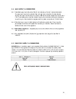
6.4  GAS SUPPLY & CONNECTION 

6.4.1 Installation pipe work should be fitted in accordance with local / national standards. 

The pipe work must not be smaller than unit gas inlet connection. If using flexible 
hosing, the hose must be sized to conform to BS 6173 and the length must not exceed 
1.5m. An isolating valve must be located close by for shut-down during an emergency 
or servicing. An inlet manifold is supplied with to enable connection to ¾” BSP inlets. 

6.4.2 If flexible hose is used, it shall comply with national requirements. These must be 

periodically examined and replaced as necessary. A retention chain must also be 
attached to the rear of the appliance. 

6.4.3 

Natural Gas Appliance

 - Supplied governor must be fitted to the rear of the appliance. 

(see section 8.9) 

6.4.4 The installation should be checked for gas tightness and purged as specified in 

IGE/UP/1. 


6.5  ELECTRIC SUPPLY & CONNECTION 

G3845F Only

 - A suitable supply cord is supplied that conforms to BSEN 50525-2-11, cable 

type H05VV-F. This appliance is designed to, and must, be connected to suitably rated 
isolator. It is recommended that the isolator be rated to 230V at 13A, 

with contact separation 

of  at least 3mm


in all poles

. If cord is damaged, it must be replaced by a suitably qualified 

person.  
 

Live 1   ( Phase 1) 

Brown 

Neutral 

Blue 

Earth 

Yellow/Green 


THIS APPLIANCE MUST BE EARTHED. 


Содержание Dominator Plus G3845

Страница 1: ...tallation and servicing instructions GAS TWIN PAN FRYER G3845 G3845F Read these instructions before use T101003 Rev No 2 Published 20 01 2019 DATE PURCHASED MODEL NUMBER SERIAL NUMBER DEALER SERVICE P...

Страница 2: ...ance and any replacement parts in a safe manner via a licensed waste handler Appliances are designed to be dismantled easily and recycling of all material is encouraged whenever practicable Dear Custo...

Страница 3: ...SYMBOLS SCREWDRIVER SPANNER COOKING OIL GREASE WARNING SPARK IGNITION FLAME VIEWPORT ALLEN KEY IGNITER C SPANNER REMOVE DEVICE PLUG REMOVER...

Страница 4: ...cock fitted in the supply pipe work The user must be familiar with the location and operation of this device in order to turn off the supply of gas in the event of an emergency This appliance has been...

Страница 5: ...ealth and safety of your business you must control any risks identified in your commercial kitchen To do this you need to think about what might cause harm to people and decide whether you are taking...

Страница 6: ...DIMENSIONS CONNECTION LOCATIONS 12 6 0 INSTALLATION 13 6 1 SITING CLEARANCES 13 6 2 VENTILATION 14 6 3 ASSEMBLY 14 6 4 GAS SUPPLY CONNECTION 15 6 5 ELECTRIC SUPPLY CONNECTION 15 6 6 COMMISSIONING 16...

Страница 7: ...8 11 PUMP 26 8 12 PUMP TIMER SETTING 27 8 13 CIRCUIT DIAGRAMS 28 8 14 WIRING DIAGRAMS 29 9 0 ACCESSORIES 30 9 1 SPLASHGUARD 30 10 0 FAULT FINDING 30 11 0 SPARE PARTS 32 12 0 SERVICE INFORMATION 33...

Страница 8: ...1 1 0 APPLIANCE INFORMATION This appliance has been CE marked on the basis of compliance with the relevant EU directives for the heat inputs gas pressures and voltages stated on the data plate...

Страница 9: ...ONENT PARTS A Dust Cover F Oil Buckets G3845F only B Baskets G Filtration Basket Mesh Filter C Fry Plate G3845F only D Crumb Catcher H Oil Return Pipe E Drain Pipe G3845 only I Basket Hanger J Drain C...

Страница 10: ...3 2 2 CONTROLS J Temperature Control N Pump Switch G3845F only K Piezo Igniter O Safety Thermostat Reset Button L Gas Control P Drain Valve G3845 Style M Drain Valve G3845F Style...

Страница 11: ...rk to achieve the stated performance of the fryer The volume of oil will increase as the oil is heated The approximate volume of cold oil when filled to the MIN level is 12 8 litres ALWAYS MAINTAIN AN...

Страница 12: ...will light at the LOW flame position This position is for preheating and maintaining temperature 2 3 6 When ready to cook turn the gas control to the HIGH position Set the temperature control as requi...

Страница 13: ...the oil has been allowed to cool Ignoring this advice may lead to burns and build up of oily condensation inside the appliance The drain valve is fitted with a spring loaded safety latch Push this lat...

Страница 14: ...ltration basket and mesh filter to clear the debris within the oil The appliance is designed so that the pump will cut off after operating for 8 minutes To continue with the filtration process simply...

Страница 15: ...e due to the safety cut out and the safety thermostat will need to be reset 2 5 2 To reset the safety thermostat first ensure the gas control is turned OFF and wait at least half an hour for the oil t...

Страница 16: ...ample are an explosive mix and should be avoided at all costs Other useful references for health and safety issues www hse gov uk Essentials of health and safety at work ISBN978 Noise at work INDG362...

Страница 17: ...dispose the old oil 3 1 5 Remove baskets Fry Plates and crumb catcher and wash it in warm soapy water Rinse and dry thoroughly before replacing them back in the appliance 3 1 6 Ensure drain valve is...

Страница 18: ...OUT WITH THESE TOLERANCES THE CAUSE MUST BE INVESTIGATED AND RECTIFIED 4 3 INJECTOR SIZES PRESSURE TABLE INJECTOR SIZES PRESSURE NATURAL GAS PROPANE G3845 2 75 1 70 G3845F 2 75 1 70 Pilot Injectors 5...

Страница 19: ...12 5 0 DIMENSIONS CONNECTION LOCATIONS...

Страница 20: ...e appliance data label The electrical installation and connections should meet the necessary requirements to local electrical wiring regulations and electrical safety guidelines We recommend Supplemen...

Страница 21: ...ance and level using feet adjusters as shown below TAKE CARE WHEN MOVING AN APPLIANCE FITTED WITH CASTORS 6 3 2 Connect appliance to gas supply and test for gas tightness see section 6 4 This applianc...

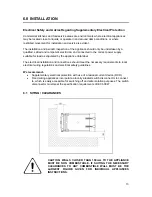
Страница 22: ...eplaced as necessary A retention chain must also be attached to the rear of the appliance 6 4 3 Natural Gas Appliance Supplied governor must be fitted to the rear of the appliance see section 8 9 6 4...

Страница 23: ...6 6 3 Natural Gas Appliance only Adjust Governor as shown in section 8 9 6 6 4 Fill pan with cold oil to the MIN mark 6 6 5 Light all pilots to ensure they all stay lit 6 6 6 Turn on main burners and...

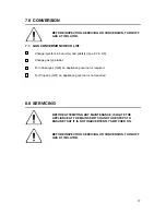
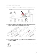
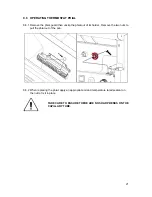
Страница 24: ...8 7 8 8 Change gas type label For natural gas G20 an appliance governor is required For Propane G31 an appliance governor is not required 8 0 SERVICING BEFORE ATTEMPTING ANY MAINTENANCE ISOLATE THE AP...

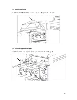
Страница 25: ...18 8 1 FRONT FASCIA 8 1 1 Removal of the front fascia allows access to the pressure test points 8 2 INNER CONTROL PANEL 8 2 1 Remove the inner control panel to gain access to the control parts...

Страница 26: ...remove the safety thermostat phial see section 8 5 8 4 GAS VALVE 8 4 1 To gain access to the gas valve remove the 4 screws that hold the gas valve bracket The valve is secured to the bracket with nut...

Страница 27: ...2 Remove the nuts holding the phial cover then unclip the phial form the cover Use a screwdriver to knockout the graphite sealant to remove the phial 8 5 3 When replacing the phial apply an appropriat...

Страница 28: ...nclip the phial out of its holder Remove the two nuts to pull the phial out of the pan 8 6 2 When replacing the phial apply an appropriate oil and temperature rated sealant on the nut to fix it in pla...

Страница 29: ...ting panel and drop the entire pilot assembly down to gain access to it 8 7 2 Remove the pilot assembly from the mounting panel to access fittings easier for the pilot gas pipe pilot injector thermoco...

Страница 30: ...8 1 Disconnect the compression fitting on both burners to remove the gas pipes 8 8 2 Remove the fixings retaining the burner tray and slide the entire burner tray assembly out to gain access to the b...

Страница 31: ...burner injector can be accessed Use a 13mm spanner to remove 8 8 4 To remove burner from the burner tray remove the two fixing screws at the front and remove the injector holder nut Slide the burner...

Страница 32: ...ection of flow GOVERNOR SUPPLIED IS MAINTENANCE FREE ENSURE THE BLUE DUST CAP COVERING THE VENT IS FITTED AND IN GOOD CONDITION 8 10 REAR ELECTRICS BOX 8 10 1 G3845F only Remove five screws to slide o...

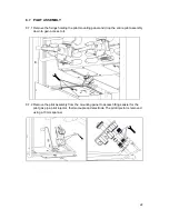
Страница 33: ...ning part through electrical box Remove two screws and lift electrical box away from unit 8 11 PUMP 8 11 1 Remove pipe fixing on pump head Remove the bottom pump access bracket by removing the two fix...

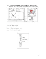
Страница 34: ...screws slightly that holds the pump Remove the pump by lifting it out of the keyway and dropping it out of the appliance 8 12 PUMP TIMER SETTING 8 12 1 Set top function to 0 8 8 12 2 Set middle funct...

Страница 35: ...28 8 13 CIRCUIT DIAGRAMS 8 13 1 G3845F Circuit Diagram...

Страница 36: ...29 8 14 WIRING DIAGRAMS 8 14 1 G3845F Wiring Diagram...

Страница 37: ...re them in place 10 0 FAULT FINDING FAULT POSSIBLE CAUSES REMEDY USER ENG Burner Pilot will not light stay lit No gas to the unit Check main gas is turned on Safety thermostat has activated Reset safe...

Страница 38: ...s never empty when the burner is ON Oil not getting up to the desired temperature Faulty thermostat Replace thermostat PROBLEM POSSIBLE CAUSES REMEDY USER ENG Surge Boiling Over loading with wet food...

Страница 39: ...lter Basket 535580037 Oil Pick Up Pipe 535620006 Suction Pipe Filter 535580052 Front Fascia 535620010 Door Assembly 535620000 Piezo Igniter 535010000 Safety Thermostat 530740023 Pump 535770077 Pump Sw...

Страница 40: ...N It is recommended to have an annual maintenance contract with a local service provider SERVICELINE CONTACT UK only Phone 441438 363 000 Warranty Policy Shortlist For our warranty policy please go to...

Отзывы: