background image

30iE - v1111 - Installation/Operation - (13/48)

2.5 Special operations

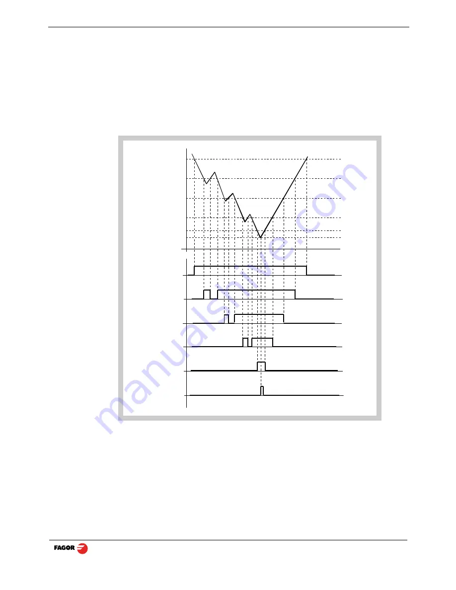
2.5.1 EDM mode

The dro activates the outputs when the axis reaches the programmed position. See

next subsection ”

Programming the levels on page 14

”.

The  are two ways to ope rate  in th is  mode dep ending  on the value   of  installation

parameter PAR20 bit 4. 
PAR20 bit 4 = 0 (the outputs are activated or deactivated when crossing the selected

level)

Home

P2

P3

P4
P5

End

O1

O2

O3

O4

O5

O6

Содержание Innova 30i-E

Страница 1: ...30i E 30i E B Installation operation manual Manual code 14460149 Manual version 1111 Software version 1 xx Fagor Automation S Coop ...

Страница 2: ...2 4 3 Datum point part zero to work with tool compensation 12 2 5 Special operations 13 2 5 1 EDM mode 13 2 5 1 1 Programming the levels 14 2 5 1 2 Deactivate the outputs 14 2 5 2 Part centering 15 2 6 Examples of how to operate with tool compensation 15 2 6 1 Inside pocket 16 2 6 2 Outside pocket 17 2 7 Access to special modes 18 2 7 1 Linear and bolt hole drilling 18 2 7 1 1 Work plane selection...

Страница 3: ... connection Connector X4 30 3 5 Easy setup 32 3 5 1 Accessing the Easy Setup mode 32 3 5 2 Operating mode 32 3 5 3 Power and machine connection 33 3 6 Installation parameters 33 3 7 Parameters to configure axis position reading and display 35 4 Appendix 43 4 1 UL seal 43 4 2 CE seal 43 4 2 1 Declaration of conformity 43 4 2 2 Safety conditions 44 4 2 3 Warranty terms 46 4 2 4 Material returning te...

Страница 4: ...ween decimal degrees and Degrees Minutes Seconds To get into and out of home search mode TOOL It stays on when operating in tool radius compensation mode Activate tool radius compensation Cancel tool radius compensation Select the current reference To access th e special functions bolt hole and linear drilling ho ld calculator part angle corner rounding To select the axis or preset it with a certa...

Страница 5: ...onding error code See the error table and PAR11 for more options Turns the DRO on or off Precautions Before disconnecting this unit from mains press this key so it saves th e current position If the unit is turned off or there is a power outage the DRO will try to save the current position If it does not have enough time to safe all the data it will display ERROR 2 when turned back on ...

Страница 6: ...o indicate the double or actual reading respectively Notes This works in this way if bit 2 of installation parameter PAR04 radius diameter of the axis has been preset as 1 commutated Hysteresis or minimum position value When carrying out certain operations such as drilling hard material EDM etc the position display may fluctuate annoyingly In these cases the operator can eliminate this oscillation...

Страница 7: ... point chosen in the feedback system linear or encoder Press this sequence to access the Home Search mode ABS In Absolute ABS when the ABS led is on it displays the distance from the present position of the axis to part zero D I In Incremental when the ABS and home LEDs are off the distance from the present position of the axis to the previous position is displayed Toggles between the ABS and incr...

Страница 8: ... without tool compensation canceled because the hole coordinates are referred to the center and no tool radius compensation is needed 2 2 1 1 Absolute mode Set the dro in absolute mode Move the axis until the display reads 14 000 B position and drill the hole Move the axis until the display reads 37 000 C position and drill the hole Move the axis until the display reads 62 000 D position and drill...

Страница 9: ...ative distance with respect to the next hole Starting at point A Preset the relative distance to the next hole See note Move the axis until the display reads 0 000 B position and drill the hole Preset the relative distance to the next hole See note Move the axis until the display reads 0 000 C position and drill the hole Preset the relative distance to the next hole See note Move the axis until th...

Страница 10: ...e machine zero point home Fagor also offers encoders with distance coded reference marks every 20 40 or 100 mm When using these distance coded reference marks there is no need to move to the 0 p osition to find the refe rences simply move a distance equ al to th e gap between marks 20 40 or 100 mm depending on the linear encoder When using an absolute encoder there is no need to search for the ref...

Страница 11: ...sts the diameter on the Y axis and the length on the Z axis Enter this value pressing this keystroke sequence Note Since only the diameter of a tool may be stored when changing a tool its dimensions must be entered again 2 4 2 Tool dimension compensation while machining To properly machine the part the tool diameter must be compensated depending on the machining direction Tool This led turns on wh...

Страница 12: ...ple of the figure the sequence would be For the X axis move the tool and touch it on the left side and press this key To preset this side to 0 See note For the Y axis move the tool and touch it on the lower side and press this key To preset this side to 0 See note Notes If installation parameter PAR11 1 just press the axis key X Y or Z to zero it The tool diameter value must be previous entered in...

Страница 13: ...is reaches the programmed position See next subsection Programming the levels on page 14 The are two ways to ope rate in th is mode dep ending on the value of installation parameter PAR20 bit 4 PAR20 bit 4 0 the outputs are activated or deactivated when crossing the selected level Home P2 P3 P4 P5 End O1 O2 O3 O4 O5 O6 ...

Страница 14: ...the following keys The X axis display shows the word COdE 060496 The displays of the DRO show PAR00 Once in regular display mode parameters PAR40 through PAR45 output levels may also be recalled by pressing this keystroke sequence so the work mode may be changed without having to go through all the previous steps 2 5 1 2 Deactivate the outputs Desactivas the digital outputs The screen will blink t...

Страница 15: ... Press the sequence 1 2 X for one axis or 1 2 Y for the other The DRO will display half of the distance covered by the tool Retract the axes until the displays read 0 0000 the tool can be placed exactly at the center of the part 2 6 Examples of how to operate with tool compensation The following illustration displays the typical application of tool compensation to make both an inside and outside p...

Страница 16: ...o to point A For that Press these keystroke sequences Compensate for the tool Move both axes until the displays read X 0 000 and Y 0 000 Go to point B For that Press these keystroke sequences Compensate for the tool Move X axis until the displays read X 0 000 and Y 0 000 And so on for the remaining points of the figure using the icon keys shown A B 30 56 10 00 X 0 000 Y 0 000 60 25 0 000 X 0 000 Y...

Страница 17: ...o to point A For that Press these keystroke sequences Compensate for the tool Move both axes until the displays read X 0 000 and Y 0 000 Go to point B For that Press these keystroke sequences Compensate for the tool Move X axis until the displays read X 0 000 and Y 0 000 And so on for the remaining points of the figure using the icon keys shown A B 18 24 10 00 X 0 000 Y 0 000 43 340 0 000 X 0 000 ...

Страница 18: ...ng 2 linear drilling 3 hold 4 calculator 5 part angle 6 corner rounding For example F 1 to access BOLT HOLE DRILLING F 4 to directly access the CALCULATOR mode 2 7 1 Linear and bolt hole drilling For 3 axis DRO s 30i M it is po ssible to select the work plane for linear or bolt hole drilling The possible work planes are XY XZ YZ 2 7 1 1 Work plane selection Note To enable this function Selection s...

Страница 19: ...irst and last hole 240º DELTA Δ angular distance between holes 60º Only requested when HOLES 0 bEtA β position of the first hole 15º To make this part Select the work plane selection See section Work plane selection on page 18 Entering data Position the tool at the bolt hole center X 37 899 Y 30 467 and press this key Enter the radius Enter the number of holes Enter the angular distance between th...

Страница 20: ...le Move the axes until the displays read X 0 000 and Y 0 000 Press this key HOLE 02 It displays this text Press this key again to show the position of the second hole Press this key to display the current position with respect to the previous hole Move the axes until the displays read X 0 000 and Y 0 000 And so on until all the holes are completed all 5 in the example X 23 105 Y 6 190 X 0 000 Y 0 ...

Страница 21: ...of the axis This comes about when it is necessary to change the tool and preset the dimension of the new one Example To change a tool at any known point of the part Touch the part with the tool Go into HOLD mode The reading for that axis freezes with the current value Select the axis Remove the tool to be replaced and insert the new one Approach the new tool to the freezing point and touch the par...

Страница 22: ...Operating with the calculator Enters the first operand in the X axis display Enters the second operand in the Y axis display Toggles between the various operations Toggles between the various trigonometric operations It carries out the operation and leaves the result on the X axis display Basic operations Display Meaning Operation ad Add Result X Y su Subtract Result X Y nu Multiply Result X Y di ...

Страница 23: ...lculation Example Calculate Y position 5 and preset the Y axis with the result Display keys Operation Display X 25 Y 10 Z 16 Goes into calculator mode X 0 Y 0 Z Ad X 0 Y 0 Z Ad Goes into RECALL mode and enters the current position in the Y axis X 10 Y 0 Z Ad X 10 Y 0 Z Ad Presets the divisor 5 X 10 Y 5 Z Ad X 10 Y 0 Z Ad Selects the divide operation X 10 Y 5 Z di X 10 Y 5 Z di Result in the X disp...

Страница 24: ...on it To do this follow this procedure Move the tool until it touches the part at any point Access the angle calculation mode Touch the part with the tool at any other point Press ENTER so the DRO calculates the angle or C to cancel the operation The X axis display will show the an gle in ten thousandths of a de gree 0 0001º and the Z axis display will do so in degrees minutes and seconds Press an...

Страница 25: ...ata Starting position The current p osition is assumed as the startin g point for the machining operation Tool dimensions If no tool has been defined diameter 0 it will request a diameter value Work plane and final position select the axes that define the desired plane XY YZ or XZ and enter the final position Note The value of the final position must be incremental or absolute according to the sel...

Страница 26: ... Installation Operation 26 48 3 DRO installation 3 1 Installation of the built in model Dimensions of the enclosure hole for inserting the DRO Built in DRO insertion Bolt ISO 7380 M4 x 10 Inox Nut DIN 985 M4 Inox ...

Страница 27: ...on 3 Mounting bracket Some of the following connectors might not be available depending on specific models X1 SUB D HD type 15 pin female connector for 1st axis feedback device X2 SUB D HD type 15 pin female connector for 2nd axis feedback device X3 SUB D HD type 15 pin female connector for the third a xis feedback device Only available at the 30i M model X4 SUB D HD type 15 pin female connector f...

Страница 28: ...t the unit is not under power It is NOT enough to turn the display off by using the on off key at the keyboard 3 3 General technical characteristics Universal Power Supply between 100V AC and 240V AC 10 at Mains frequency between 45 Hz and 400 Hz Between 120Vdc and 300 Vdc It withstands power outages of up to 20 milliseconds 10 year memory backup of installation parameters when the unit is off The...

Страница 29: ...n 250 mA at the 5V input Admits square wave signal TTL Maximum frequency 250 KHz minimum gap between flanks 950 nsec Phase shift 90º 20º hysteresis 0 25 V Vmax 7V maximum input current 3mA High threshold logic state 1 2 4V VIH 5V Low threshold logic state 0 0 0V VIL 0 55V Feedback connection Connectors X1 X2 and X3 Pin Signal Function 1 A Input for feedback signals 2 A 3 B 4 B 5 I0 6 I0 7 Alarm 8 ...

Страница 30: ...reshold voltage logic state 1 18V Low threshold voltage logic state 0 5V Typical consumption of each input 5mA Maximum consumption of each input 7mA Characteristics of the outputs Rated voltage 24 V AC or DC Maximum voltage 47 V AC or DC Protection against over voltage Maximum load current 100mA Protection against over current Activation time 3ms Deactivation time 3m Inputs Input output connection...

Страница 31: ...llation Operation 31 48 Outputs The outputs that will be connected to an inductive load must have a 1N4000 diode or similar in anti parallel Open collector outputs Open emitter outputs LOAD Common LOAD LOAD LOAD Common ...

Страница 32: ...ssing the Easy Setup mode Press CLEAR OFF And instead of entering the parameters accessing code key in 555 The axes displays will show Setup meaning that the feedback is not set up yet 3 5 2 Operating mode Move the axis to the desired origin or zero point and press the axis key The display shows START Move the axis in the direction that you wish to define as positive all the way to the end of the ...

Страница 33: ...rs These DROs have a number of installation parameters to configure it for a particular application The way these parameters are displayed depe nds on whether they are general or particular for each axis If it affects the axes the parameter number PAR appears on each axis display and the corresponding axis key must be pressed to modify it If it is a general parameter and there are more than one ax...

Страница 34: ...his key to save the displayed value Press this key to cancel the modification Move through parameters Press the ENTER key to go on to the next parameter or Press this key to return to the previous one To quit the parameter editing mode Press this key To go to a particular parameter To go directly to a particular parameter without going through the previous ones once in parameter editing mode press...

Страница 35: ...m 1 leadscrew pitch in inches Rotary axis 0 degrees 1 seconds Note These units refer to feedback pulses not to the position display 4 Type of axis 0 Linear 1 Rotary 3 Not being used at this time 2 Not being used it must be set to 0 1 Counting direction 0 normal 1 reverse If an axis count increases or decreases in the opposite direction to the one desired change the value of this digit PAR01 Feedba...

Страница 36: ...s per turn of the encoder P Leadscrew pitch in mm turn R Resolution in mm pulse F Multiplying factor to be applied PAR03 External multiplying factor when using distance coded reference marks or TTL signals Independent for each axis It is not required when using absolute feedback Options 1 5 10 20 25 50 Factory setting 1 Note In the table X means that the bit is irrelevant p P RxF Feedback paramete...

Страница 37: ...red PAR07 Combine the reading of an axis Independent for each axis Indicates the number of the axis to be combined 0 means not to combine any other axis 1 X a xis 2 Y 3 Z With th e negative sign t he other axis count will be subtracted Factory setting 0 The axis being combined must have the same resolution as the one combined with PAR01 PAR02 PAR03 Possible values 2 to 2 20i M 3 to 3 30i M Note Wh...

Страница 38: ...with respect to the reference zero of the scale independent for each axis Usually the machine reference zero reference mark of the linear encoder does not coincide with the absolute zero to be used Therefore when using standard Io s this para meter must be assigned the value of the distance from the machine zero point to the feedback reference point Numeric value in resolution units for each axis ...

Страница 39: ...If PAR08 bit 2 1 when the axis exceeds the travel distance between both parameters the relevant display starts blinking until it is positioned within these limits PAR14 Binary type home search setting Digit 8 7 Not being used at this time they must be set to 0 6 If 1 it indicates mandatory home search on power up 5 Direction of the distance coded Io 0 Increasing 1 Decreasing 4 1 Pitch of the dista...

Страница 40: ...pensation point must have at least one point with no error error 0 Select the desired axis and enter the number of points to be used for this axis up to 40 zero means that there is no compensation table for the axis Where POS 1 is the point number to enter and ERROR 1 the amount of error to be compensated Multi point leadscrew error compensation table in mm Point Nr Position Error to be compensate...

Страница 41: ... back on 4 0 The outputs are activated or deactivated when crossing the selected level 1 Deactivate the outputs when returning to position home 3 2 1 Apply hysteresis onto the 3rd 2nd and 1st axis respectively PAR21 Active level of the inputs Only the first 4 digits have a meaning 0 Input active low 1 Input active high Key 1 corresponds to input 1 key 2 to input 2 and so on PAR23 Active level of t...

Страница 42: ...ponds to the number of decimals to be displayed in mm and the second digit to the number of decimals in inches When selecting a 0 value or a value greater than the number of decimals of PAR01 it will display the factory set number of decimals Note It has no effect on rotary axes PAR65 It enables various functions of the dro Digit 8 1 To enter the tool length 7 1 To enter the tool diameter 6 1 To c...

Страница 43: ...he machines ELECTROMAGNETIC COMPATIBILITY EN 61000 6 4 Emission EN 55011 Radiated Class A Group 1 EN 55011 Conducted Class A Group 1 EN 61000 3 2 Harmonics EN 61000 3 3 Flickers EN 61000 6 2 Immunity EN 61000 4 2 Electrostatic discharges EN 61000 4 3 Radiofrequency Radiated Electromagnetic Fields EN 61000 4 4 Bursts and fast transients EN 61000 4 5 Shockwaves EN 61000 4 6 Conducted disturbance ind...

Страница 44: ...oid electrical discharges and fire hazards do not apply electrical voltage outside the range indicated in chapter 2 of this manual Ground connection In order to a void electrical discharges connect the ground terminals of all the modules to the main ground terminal Before connecting the inputs and outputs of this unit make sure that all the grounding connections are properly made Before powering t...

Страница 45: ...rful loads connected to the same AC power line as this equipment Nearby portable transmitters Radio telephones Ham radio transmitters Nearby radio TC transmitters Nearby arc welding machines Nearby High Voltage power lines Disturbance generating elements of the machine Etc Safety symbols Symbols which may appear on the manual WARNING symbol It has an associate d text indicating tho se actions or o...

Страница 46: ...d has been manipulated by personnel authorized by FAGOR If once the service call or repair has been completed the cause of the failure is not to be blamed the FAGOR product the customer must cover all generated expenses according to current fees No other implicit or explicit warranty is covered and FAGOR AUTOMATION shall not be held responsible under any circumstances of the damage which could be ...

Страница 47: ...ts a re as they sho uld be If th ere are OK disconnect the feedback connectors one by one If the dro comes on it means a feedback failure If the fault persists get in touch with Fagor Automation s Customer Services Department about it Error codes Error Description FAGOR dro Power outage or turned off with main switch after saving the data Error 02 The unit has been turned off without previously pr...

Страница 48: ... the materials the equipment is made with Do not use high pressure compressed air to clean the item as this could give rise to an accumulation of charges which in turn lead to electrostatic discharges The plastics used in the front panel of the DRO stand up to Grease and mineral oils Alkalis and bleaches Dissolved Detergents Alcohol Avoid the effect of solvents such as Chlorohydrocarbons Benzol Es...

Отзывы: