Power supplies
POWER SUPPLIES
Re
gene
rative regul
ated pow
er
su
ppli
es
2.
83
DDS
HARDWARE
Ref.1310
Remember that the purpose of connecting an auxiliary power supply APS-
24 to the DC bus of a DDS system is to ensure the supply to all the con-
trol circuits of the power supply and of the drive modules connected to the
DC bus in case of a mains power outage in the auxiliary power supply en-
suring a controlled stop of the moving axes instead of braking out of con-
trol by friction.
Bear in mind that although RPS power supplies come with an internal
auxiliary power supply offering 3 outputs with 24 V DC and a total of 8 A,
192 W, this power may not be enough to feed the control circuits of all the
modules connected or other elements (e.g. a fan). That is why it may be
necessary to also install an APS-24 auxiliary power supply to guarantee
all the power needed.
The APS-24 auxiliary power supply offers 3 outputs with 24 V DC and a
total of 10A, 240 W.
For further information about the auxiliary module APS-24, see chapter
in this manual.
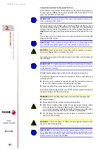
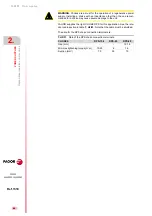
Connection of the chokes
These chokes
called choke RPS are connected in series with each phase
of the three-phase line between the MAINS FILTER
A and the RPS
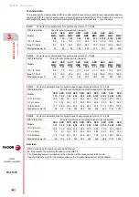
power supply module. The following table shows the choke associated
with the power supply:
For further detail, see chapter
and chapter
in this manual.
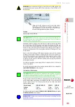
WARNING.
Never install an APS-24 to the DC bus of a DDS system with
a regenerative power supply RPS if the reference of the APS-24 is PF
23A or older.
F. H2/43
Version label of the APS-24.
Observe the PF reference on the versions label.
Depending on this reference, it will be possible to con-
nect the APS-24 or not to the DC bus of the DDS sys-
tem with RPS regenerative power supplies.
INFORMATION.
It will not be necessary to install external protection fus-
es in these power lines of the auxiliary power supply. They are already in-
tegrated in the power supply itself.
i
INFORMATION.
RPS regenerative regulated power supplies, unlike XPS,
regenerative power supplies do not have connection terminals called CH1
and CH2 at the bottom of the module for connecting the chokes.
i
Power supply
RPS-80 / RPS-75
RPS-45
RPS-20
3-phase
choke
Choke
RPS-75-3
Choke
RPS-45
Choke
RPS-20
MANDATORY.
Chokes are a must to limit the current circulating from the
power bus to mains.
Содержание DDS
Страница 1: ...DRIVE DDS Hardware manual Ref 1310...
Страница 6: ...I 6 DDS HARDWARE Ref 1310...
Страница 9: ......
Страница 10: ......
Страница 11: ......
Страница 12: ......
Страница 16: ...16 Ref 1310 DDS HARDWARE...
Страница 30: ...1 DESCRIPTION 30 Description DDS HARDWARE Ref 1310...
Страница 94: ...2 POWER SUPPLIES 94 Power supplies DDS HARDWARE Ref 1310...
Страница 188: ...3 DRIVE MODULES 188 Drive modules DDS HARDWARE Ref 1310...
Страница 204: ...4 AUXILIARY MODULES 204 Auxiliary modules DDS HARDWARE Ref 1310...
Страница 232: ...SELECTING CRITERIA 5 232 Selection criteria DDS HARDWARE Ref 1310...
Страница 266: ...7 CABLES 266 Cables DDS HARDWARE Ref 1310...
Страница 312: ...8 INSTALLATION 312 Installation DDS HARDWARE Ref 1310...
Страница 326: ...9 FUNCTIONAL SAFETY 326 Functional safety DDS HARDWARE Ref 1310...
Страница 354: ...10 CONNECTION DIAGRAMS 354 Connection diagrams DDS HARDWARE Ref 1310...
Страница 378: ...12 SALES REFERENCES 378 Sales references DDS HARDWARE Ref 1310...
Страница 384: ...13 COMPATIBILITY 384 Compatibility DDS HARDWARE Ref 1310...
Страница 385: ......

