Drive modules
DRIVE MODULES
Co
mpact d
riv
es
3.
165
DDS
HARDWARE
Ref.1310
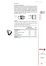
The following table shows the values for gap, tightening torque (wire en-
try holes) and other data regarding the screw-on terminals of the ballast
connectors according to drive model:
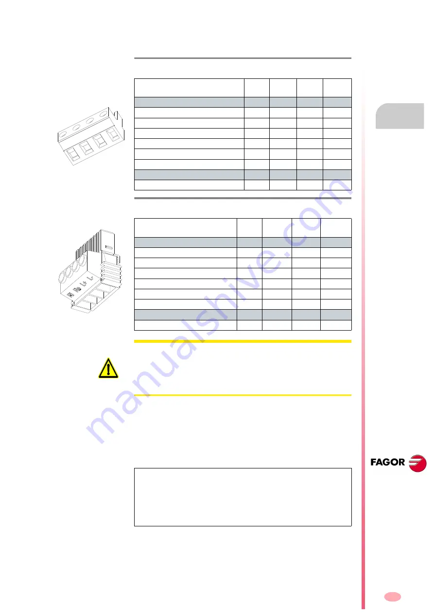
The terminals (Ri, Re and L+) are used to configure the Ballast circuit
whose purpose is to dissipate the energy generated while braking the mo-
tor.
By jumpering the terminals (Ri and L+), the system is configured so as to
work with the internal resistor of the compact drive module; this configura-
tion, as mentioned earlier, can only be set for ACD/SCD/CMC 1.08/1.15
models.
Up to 45 °C (113 °F), this resistor dissipates the power indicated in the
technical data table. See table
.
All the modules carry a protection against over-temperature which issues
an error E301 when reaching 105 °C (221 °F).
T. H3/20
Technical data of aerial connector for the external braking resis-
tor (Ballast) on ACD/SCD/CMC 1.15/1.25/2.35/2.50 drives.
ACD/SCD/CMC
1.08
1.15
1.25
2.35
2.50
Connector data
Nr of poles
4
4
4
4
Gap (mm)
7.62
7.62
7.62
7.62
Min/max tightening torque (Nm)
0.5/0.6 0.5/0.6 0.5/0.6 0.5/0.6
Screw thread
M3
M3
M3
M3
Min./max. section (mm²)
0.2/2.5 0.2/2.5 0.2/2.5 0.2/2.5
Rated current In
(A)
12
12
12
12
Wire data
Length to strip (mm)
7
7
7
7
T. H3/21
Technical data of aerial connector for the external braking resis-
tor (Ballast) on SCD 2.75.
SCD
2.75
Connector data
Nr of poles
4
Gap (mm)
7.62
Min/max tightening torque (Nm)
0.7/0.8
Screw thread
M3
Min./max. section (mm²)
0.2/6
Rated current In
(A)
41
Wire data
Length to strip (mm)
10
x1
x1
WARNING.
On ACD/SCD/CMC 1.08/1.15 modules, if an external Ballast
resistor (for braking) is going to be connected, make sure that its Ohm va-
lue is exactly the same as that of the internal Ballast resistor. See table
which indicates this value. The rest of the compact modules have
no internal Ballast resistor; therefore, always install the external Ballast
resistor supplied by FAGOR with the unit.
NOTE.
Never configure
models
ACD/SCD/CMC 1.25/2.35/2.50
and
SCD
2.75
with internal Ballast resistor (jumper between Ri and L+). These
modules do not have an internal Ballast resistor. If this warning is ignored
and a (L+, Ri) configuration is used instead of (L+, Re), either
unknowingly or inadvertently, there is no risk of destroying the module,
but the power bus will not charge.
Remember that pin Ri has no function
in these modules.
Содержание DDS
Страница 1: ...DRIVE DDS Hardware manual Ref 1310...
Страница 6: ...I 6 DDS HARDWARE Ref 1310...
Страница 9: ......
Страница 10: ......
Страница 11: ......
Страница 12: ......
Страница 16: ...16 Ref 1310 DDS HARDWARE...
Страница 30: ...1 DESCRIPTION 30 Description DDS HARDWARE Ref 1310...
Страница 94: ...2 POWER SUPPLIES 94 Power supplies DDS HARDWARE Ref 1310...
Страница 188: ...3 DRIVE MODULES 188 Drive modules DDS HARDWARE Ref 1310...
Страница 204: ...4 AUXILIARY MODULES 204 Auxiliary modules DDS HARDWARE Ref 1310...
Страница 232: ...SELECTING CRITERIA 5 232 Selection criteria DDS HARDWARE Ref 1310...
Страница 266: ...7 CABLES 266 Cables DDS HARDWARE Ref 1310...
Страница 312: ...8 INSTALLATION 312 Installation DDS HARDWARE Ref 1310...
Страница 326: ...9 FUNCTIONAL SAFETY 326 Functional safety DDS HARDWARE Ref 1310...
Страница 354: ...10 CONNECTION DIAGRAMS 354 Connection diagrams DDS HARDWARE Ref 1310...
Страница 378: ...12 SALES REFERENCES 378 Sales references DDS HARDWARE Ref 1310...
Страница 384: ...13 COMPATIBILITY 384 Compatibility DDS HARDWARE Ref 1310...
Страница 385: ......


