background image

  

Installation

INSTAL

LAT

ION

C

onne

cti

on 

of the

 con

trol

 a

nd 

communica

tions 

signa

ls

8.

309

DDS

HARDWARE

Ref.1310

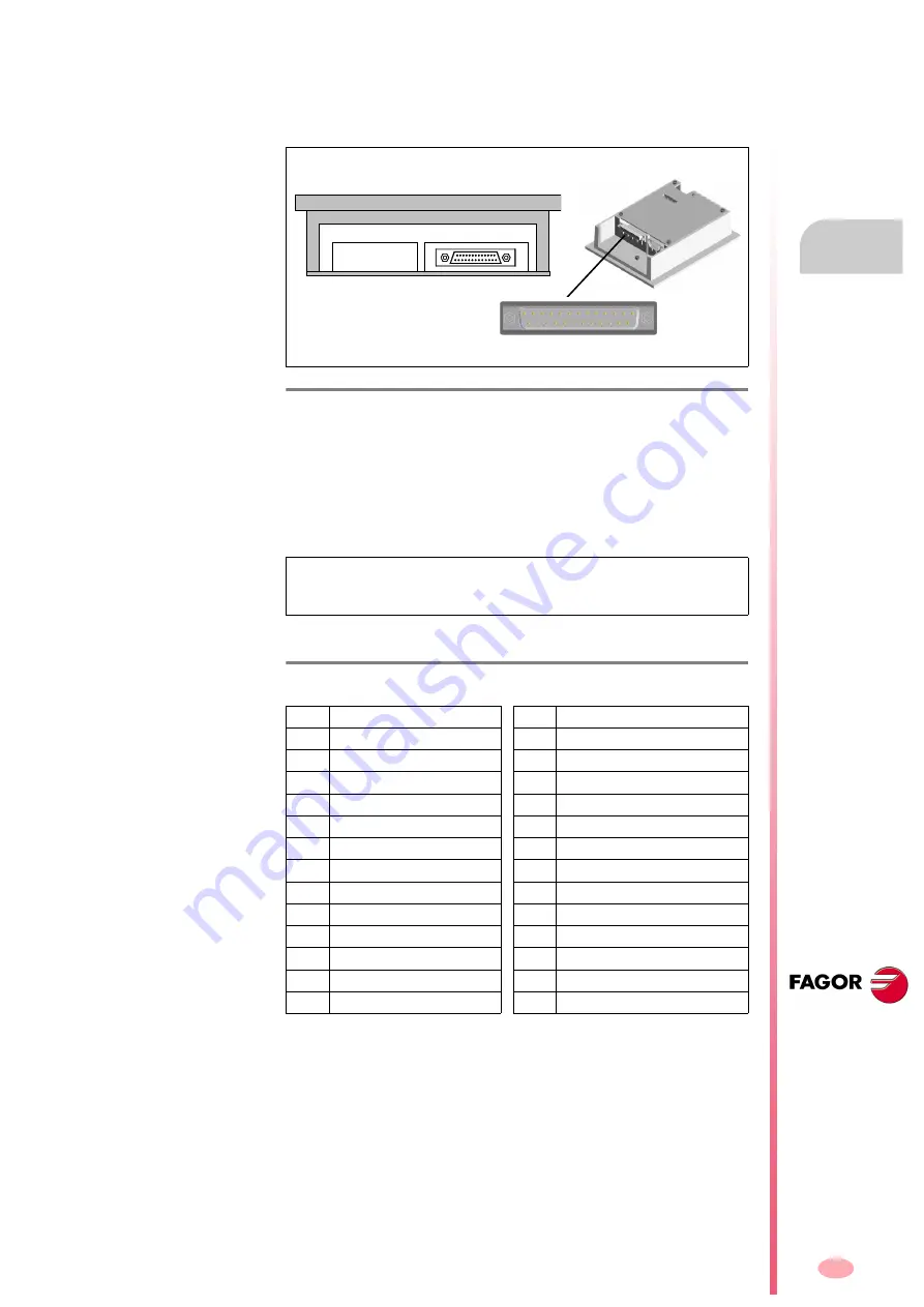
RS-232/422 serial line connection with an ESA video terminal

The RS-232/422 connection of the ESA terminal with the drives is made
through the MSP connector located at the bottom of the VT module.


See

figure:

The MSP serial port (Multi Serial Port) is a part of any ESA video termi-
nal and is used to connect it with other devices. Hence, the project is
transferred from the PC to the VT through this port.

This port is accessed from a 25-pin female SUB-D connector and may es-
tablish communication with other devices through RS-232, RS-422, RS-
485 and C.L. (TTY-20 mA) protocols.

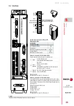
The pinout of the MSP connector is described in the following table:

F. H8/41

MSP connector of the ESA video terminal for the RS-422 connection.

NOTE. 

Pin 16 does not contemplate communicating with any type of

load. Any disturbance going into this pin can damage the video terminal
and the process.

T. H8/6

Pinout of the MSP connector. 

* C.L. means < Current Loop >.

Pin

Signal

Pin

Signal

1

Not connected

14

IKT OUT

2

TxRS232 OUT

15

IKR OUT

3

RxRS232 IN

16

+5 V DC (reserved)

4

RTS RS232 OUT

17

Not connected

5

CTS RS232 IN

18

* R x C.L. +IN

6

Not connected

19

Not connected

7

GND

20

Not connected

8

Not connected

21

Not connected

9

* TxC.L. + OUT

22

IN/OUT

10

TxRx485-IN/OUT

23

TOUT

11

* TxC.L. - OUT

24

RxRS422 -IN

12

TxRS422 - OUT

25

* R x C.L. - IN

13

RIN

Sub-D, F25 

- Front view -

[ Sub-D, F25 ]

1

13

14

25

ESA panel (VT 150W)

Bottom view

1

13

25

14

Содержание DDS

Страница 1: ...DRIVE DDS Hardware manual Ref 1310...

Страница 2: ...at in formation and it will be the user s responsibility to use it Responsibility and warranty claims are excluded in case of shipping damage wrong usage of the unit in wrong environments or when not...

Страница 3: ...nd its associated drive 205 Asynchronous spindle motor and servo drive selection 211 Drive selection 217 Power supply selection 218 Capacitor module selection guide 228 Ballast resistor selection guid...

Страница 4: ...338 Diagrams with a PS 25B4 power supply 340 Diagrams with a XPS power supply 342 Diagrams with an RPS XX power supply 344 Compact system diagrams with SERCOS connection 346 Compact system diagrams w...

Страница 5: ...CON 2 board 380 VECON 3 board 381 VECON 4 board 381 Boot for VECON 2 381 Boot for VECON 3 381 Boot for VECON 4 381 SERCOS card 16 MBd 381 CAN board 382 CAPMOTOR x boards 382 VECON X boards 382 CAPMOTO...

Страница 6: ...I 6 DDS HARDWARE Ref 1310...

Страница 7: ...INERY IEC 60204 1 2005 A1 2009 Machinery safety Electrical equipment of the machines Part 1 General requirements IEC 61800 3 2004 Category C2 Specific standard on electromagnetic compatibility for ser...

Страница 8: ...ed in the EC Type Examination T V S D Are excluded from the scope of the EC Type Examination T V S D equipment with CAN communica tion and Drives In Mondrag n May 2012 AXD X XXX A1 X X AXD X XXX SI X...

Страница 9: ......

Страница 10: ......

Страница 11: ......

Страница 12: ......

Страница 13: ...apdo 144 CP 20500 Arrasate Mondrag n Gipuzkoa Spain www fagorautomation com info fagorautomation es ABOUT THIS MANUAL MAN REGUL IN STAN Code 04754001 MAN REGUL IN AVANZ Code 04754021 DANGER In order t...

Страница 14: ...options Bear in mind that some of the features or applications described in this manual depend on the soft ware version installed These considerations are reflected in the man_dds_soft pdf manual supp...

Страница 15: ...nit and serial number 3 In case of failure also indicate the symptom and a short description of the failure 4 Protect the unit wrapping it up with a roll of polyethylene or with similar material 5 Pad...

Страница 16: ...16 Ref 1310 DDS HARDWARE...

Страница 17: ...implemented 0112 FXM motors at 400 15 V AC MMC and CMC drives ACD SCD 1 08 1 15 drive compact Crowbar resistor ER 18 1800 and ER 18 2200 RS 422 interface for MMC and CMC drives 0303 New drive SPD 2 85...

Страница 18: ...ternal 18 1800 W Ballast resistor that is supplied as an acces sory in certain units for 18 1800W with internal thermostat External Ballast resistor ER 18 2200 by ER TH 18 2200 with internal thermosta...

Страница 19: ...d in this manual Cumply always with the current safety standards the indicated conditions and the technical data Analyze risks related to the application before using the unit and take the proper safe...

Страница 20: ...sures given by EMC Malfunctions due to ignoring electromagnetic compatibility can cause unexpected system behav ior Do the whole wiring carefully according to the measures given by EMC Do not adjust t...

Страница 21: ...the unit Write down this value in the maintenance plan of the instal lation Do not use the safety function after that date Safety symbols Symbols that may appear in this manual Symbols that the produc...

Страница 22: ...to us the warranty period ends 15 months from when the product left our warehouse Fagor is committed to repairing and replacing its products from the time when the first such product was launched up...

Страница 23: ...als blows etc that could damage it Before turning the unit on verify that the ground connections have been made properly See chapter 8 INSTALLATION of this manual In case of a malfunction or product f...

Страница 24: ...ations regarding the installation of motors and modular drives power supplies and ac cessories such as cables connectors etc man_dds_comp_quick_ref pdf only in english It describes each element that m...

Страница 25: ...vious diagram will be explained in detail in the following chapters F H1 1 DDS servo drive system description Mains Power switch MAINS FILTER A 1 Motor E R Motor with encoder or resolver position Tran...

Страница 26: ...Differential breaker Optional Transformer or auto transformer Optional Power switch Mandatory Mains filter MAINS FILTER A Mandatory Non regenerative power supplies PS Regenerative power supplies XPS R...

Страница 27: ...FXM FM7 FM9 SPM Synchronous motors Asynchronous motors Capacitor module CM 1 60 It is connected in parallel to the power bus 600 V DC Resistor modules ER TH x x or ER TH 18 x FAN They are connected to...

Страница 28: ...ion Motors Power supply module Drive modules Auxiliary modules Stage 3 Connection configuration See block diagrams See connection diagrams See dimension drawings Power and signal cable selection Sugge...

Страница 29: ...1K4 25 C to 60 C Transport Damp heat test steady state Acc to IEC 60068 2 78 IEC 61800 5 1 Power Supply disconnected 40 C 2 C and 93 2 3 non condensing Ambient temperature Acc to IEC 61800 2 Equipment...

Страница 30: ...1 DESCRIPTION 30 Description DDS HARDWARE Ref 1310...

Страница 31: ...supplies when they provide a DC voltage output de pending on mains voltage and its exceeding energy is dissipated as heat in electrical resistors Regenerative power supplies when they provide a DC vol...

Страница 32: ...ey are The PS 25B4 supplies 25 kW and includes an internal auxiliary 24 V DC power supply for the control circuits of the modular drives The over volt age and ballast alarm activation levels are the o...

Страница 33: ...cuit on off 768 V DC 760 V DC Minimum external Ballast resistance 9 Filter capacity 750 F 900 V DC Energy stored in the capacitors 0 5 C V Maximum SYSTEM OK contact voltage 125 V AC 150 V DC Maximum S...

Страница 34: ...2x ER TH 18 1100 2 6 kW 4 0 kW 2x ER TH 18 1800 2x ER TH 18 2200 Power X1 RIBON CABLE SYSTEM SPEED ENABLE ERROR RESET GND RELAY CONTACT N A SYSTEM OK CHASSIS 0VDC 24VDC POWER SUPPLY POWER L1 L2 L3 GRO...

Страница 35: ...ee phase mains 2 Power connector for the external Ballast resistor connection 3 Ground connection for the mains cable 4 Power Bus supplying power to the drive modules through metal bars X1 Connector f...

Страница 36: ...nternal resistor or RM 15 module already discontinued im plies disabling the I2t protection There is no risk of destroying the resis tor because they both carry their own thermostat for their protecti...

Страница 37: ...V DC Maximum SYSTEM OK contact voltage 1 A Width 77 mm 3 03 in Approx mass 6 0 kg 13 2 lb Power dissipated at maximum load 180 W 1 See derating curves in case of high temperatures Connection of the au...

Страница 38: ...TH 18 1000 FAN 3 0 kW 4 0 kW ER TH 18 1500 FAN ER TH 18 2000 FAN SYSTEM SPEED ENABLE ERROR RESET GND RELAY CONTACT N A SYSTEM OK X2 POWER L1 L2 L3 GROUND POWER SUPPLY GROUND AUXILIARY POWER L1 L2 POW...

Страница 39: ...rs X1 Connector for inter module communication X2 Connector for the basic control signals X3 Input connector supplying from mains to the auxiliary power supply integrated into the module The mains pow...

Страница 40: ...re OVER CURRENT The red led indicates that there is an over current error at the 24 V DC output ON The green led it indicates that there are 24 V DC at the output Ballast resistor selection The non re...

Страница 41: ...own protection For the switch combination shown in the figure and verified in the table the ballast resistor selected would correspond to the ER TH 18 1800 NOTE This is the current model with three m...

Страница 42: ...minals Connector data PS 25B4 PS 65A Gap mm 10 16 Min max tightening torque N m 1 2 1 5 6 8 Screw thread M4 M6 Min max section mm 0 5 16 16 50 Rated current In A 76 150 Wire data Length to strip mm 10...

Страница 43: ...the display On PS 25B4 power supplies the power bus will not be charged Here is a graphic representation of the two possible configurations The following table shows the values for gap tightening tor...

Страница 44: ...e of the three mains phases at the input of the module This startup process begins when the FAULT indicator stops blinking and ends when the status indicator DC BUS ON turns on F H2 10 Derating curves...

Страница 45: ...the control circuits of the modules than what the internal auxiliary power supply can provide when installing a lot of drive modules Observe that the APS 24 auxiliary power supply offers 3 outputs wit...

Страница 46: ...connector The power supply module may be controlled through connector X2 F H2 11 Connection of the internal bus between modules through connector X1 F H2 12 Control of the power supply module through...

Страница 47: ...onnector X2 Connector data PS 25B4 PS 65A Nr of poles 7 10 Gap mm 5 08 5 08 Min max tightening torque N m 0 5 0 6 0 5 0 6 Screw thread M3 M3 Min max section mm 0 2 2 5 0 2 2 5 Rated current In A 12 12...

Страница 48: ...to the PS 25B4 1 2 X3 PS 25B4 3 400 460 VAC Phoenix 7 62 mm 1 3 Phoenix 5 08 mm 1 2 X6 3 24 VDC 0 VDC 1 3 X4 X5 INFORMATION There is no need to install external protection fuses in these power lines T...

Страница 49: ...ies to the system will act as follows 1 The green indicator light DC BUS ON will turn off indicating that the power supply will stop supplying voltage to the power bus 2 The red FAULT light will be on...

Страница 50: ...an return 20 kW to mains It inte grates an auxiliary 24 V DC power supply to feed the control circuits of the modular drives Consequently it will not need an APS 24 to perform this function The XPS 65...

Страница 51: ...4 V 192 W Mains consumption to generate 24 V DC 0 72 A 400 V AC 0 63 A 460 V AC Internal Ballast resistance power 1 18 520 W 9 1800 W Energy pulse to be dissipated 18 kW 0 6 s kW Ballast circuit ON OF...

Страница 52: ...x ER TH 18 1500 FAN 2x ER TH 18 2000 FAN XPS 25 25 kW Mains 20 kW 520 W Power Internal Ballast Drives 950 W ER TH 18 1100 2 0 kW ER TH 18 1000 FAN 3 0 kW 4 0 kW ER TH 18 1500 FAN ER TH 18 2000 FAN To...

Страница 53: ...D POWER SUPPLY GROUND AUXILIARY POWER L2 L1 STATUS MANAGEMENT MODULE ERRORS START UP CIRCUIT POWER SUPPLY CONTROL MANAGEMENT OF INTERMEDIATE CIRCUIT EXTERNAL CHOKE CONNECTION L Re Ri L L INTERMEDIATE...

Страница 54: ...r inter module communication X2 Connector for the basic control signals X3 Input connector supplying from mains to the auxiliary power supply integrated into the module The mains power is received thr...

Страница 55: ...gener ating mode DC BUS ON The green led indicates that the module is supplying all its power at the bus Lights indicating the status of the auxiliary power supply The regenerative power supply XPS 25...

Страница 56: ...X1 Connector for inter module communication X2 Connector for the basic control signals X3 Input connector supplying from mains to the auxiliary power supply integrated into the module The mains power...

Страница 57: ...egener ating mode DC BUS ON The green led indicates that the module is supplying all its power at the bus Lights indicating the status of the auxiliary power supply The regenerative power supply XPS 6...

Страница 58: ...mains connection Connector data XPS 25 XPS 65 Min max tightening torque N m 2 0 2 3 6 8 Screw thread M5 M6 Min max section mm 0 5 16 16 50 Rated current In A 76 150 Wire data Length to strip mm 16 24...

Страница 59: ...t over temperature which triggers error E301 on the display when reaching 105 C 221 F Derating curves The power that may be dissipated through the internal ballast resistor lo cated inside the power s...

Страница 60: ...icator DC BUS ON turns on WARNING Never connect the power bus while the system is running There are voltages of about 600 V DC MANDATORY The tightening torque of these terminals must be between 2 3 an...

Страница 61: ...PS 65 offer the connection ter minals labeled CH1 and CH2 at the bottom of the module for connecting the choke See figure F H2 17 and figure F H2 18 This inductive device is a must to limit the curren...

Страница 62: ...2 F H2 23 Connection of the internal bus between modules through connector X1 F H2 24 Control of the power supply module through connector X2 X1 1x 7 1 Gnd System Speed Enable System ok 1 2 3 4 5 6 7...

Страница 63: ...voltage through connectors X4 X5 and X6 These three connectors are identical and offer greater connecting flexibility T H2 20 Description of the pins of connector X2 1 Error RESET System error RESET i...

Страница 64: ...5 0 2 2 5 Rated current In A 12 12 Wire data Length to strip mm 7 7 T H2 22 Data of the 3 identical plug in connectors for X4 X5 and X6 Data of each connector XPS 25 XPS 65 Nr of poles 3 3 Gap mm 5 0...

Страница 65: ...ge to the power bus 2 The red FAULT light will be on permanently With the Error RESET input pin 1 it is possible to eliminate the errors at the drives that are part of the system see chapter 14 resett...

Страница 66: ...V AC and 460 10 V AC with a mains frequency of 50 60Hz and can consume and return to mains sinusoidal DC power with a maximum power factor close to 1 Unlike XPS regenera tive power supplies their bus...

Страница 67: ...ins NOTE PRIOR TO INSTALLATION Before installing an RPS power supply when using non FAGOR motors re member that INFORMATION They all integrate an auxiliary 24 V DC 8 A power supply to feed its own con...

Страница 68: ...cuit 24 V DC Three phase 50 60 Hz with a voltage range between 400 10 and 460 10 V AC Mains consumption to generate 24 V DC 0 7 A Output voltage of the auxiliary power 24 V DC 5 Max current supplied 8...

Страница 69: ...gram RPS 20 20 kW in S1 Mains Power Drives 26 kW in S6 40 20 kW in S1 26 kW in S6 40 RPS 45 45 kW in S1 Mains Power Drives 59 kW in S6 40 45 kW in S1 59 kW in S6 40 RPS 75 75 kW in S1 Mains Power Driv...

Страница 70: ...upply 8 kHz Tamb Pn power in S1 PS6 power in S6 40 in C in F in kW in kW 35 95 80 0 104 0 40 104 80 0 104 0 45 113 80 0 104 0 50 122 76 6 99 5 55 131 72 0 93 6 60 140 67 3 87 5 F H2 28 Power derating...

Страница 71: ...9 55 131 37 4 48 6 60 140 33 2 43 1 F H2 30 Power derating on RPS 45 power supply for fc 8 kHz T H2 28 Power derating on RPS 20 power supply 8 kHz Tamb Pn power in S1 PS6 power in S6 40 in C in F in k...

Страница 72: ...factor indicates that for a 10 minute cycle it works at constant power for 4 minutes P S6 40 and without load for 6 minutes 0 4 x rated cur rent Pn Cycle at Pmax without previous load Periodic intermi...

Страница 73: ...NAGEMENT MODULE ERRORS DRIVER IGBT L1 L2 L3 24VDC 0VDC CHASSIS X2 PWM ENABLE SYSTEM SPEED ENABLE GND RELAY CONTACT N A SYSTEM OK X6 POWER SUPPLY LINE FEEDBACK L1 L2 L3 1 Status xPS xx It is an AND of...

Страница 74: ...rs X1 Connector of the integrated auxiliary three phase power supply X2 Output connector of the auxiliary 24 V DC power supply integrated into the module X3 Connector to be used to open close the main...

Страница 75: ...X1 Connector of the integrated auxiliary three phase power supply X2 Output connector of the auxiliary 24 V DC power supply integrated into the module X3 Connector to be used to open close the main i...

Страница 76: ...rs X1 Connector of the integrated auxiliary three phase power supply X2 Output connector of the auxiliary 24 V DC power supply integrated into the module X3 Connector to be used to open close the main...

Страница 77: ...tegrated auxiliary three phase power supply X2 Output connector of the auxiliary 24 V DC power supply integrated into the module X3 Connector to be used to open close the main internal contactor pins...

Страница 78: ...DC BUS It indicates therefore that there is no error and that the mains phases are on 1 state of the operating modes REGEN Amber LED on It indicates that the module is working in ener gy regenerating...

Страница 79: ...n the one mains can provide See the note below for switch configuration option 1 If the mains voltage is 430 V AC The voltage that the DC BUS can supply is 1 41x430 608 V DC Therefore we must select a...

Страница 80: ...4 12 L3 L2 L1 From mains S T R N L1 L2 L3 2 The RST phases may be connected in any sequence at the power connector Cable without connectors MPC 4x mm2 POWER CONNECTOR Choke RPS XX Important note Make...

Страница 81: ...ast circuit one off the shelf will have to be installed F H2 42 Terminal strip for connecting the mains voltage input T H2 30 Data of the pins of the mains voltage sensor connector See connector 2 of...

Страница 82: ...tor stops blinking and the status indicator DC BUS ON turns on MANDATORY Use the terminals of the power bus located at the end ea siest to install the DDS system MANDATORY All the modules powered with...

Страница 83: ...es These chokes called choke RPS are connected in series with each phase of the three phase line between the MAINS FILTER A and the RPS power supply module The following table shows the choke associat...

Страница 84: ...ble must be shielded The data for the RPS choke connection terminals is WARNING Chokes are a must for the operation of a regenerative power supply Installing a choke with an inductance other than the...

Страница 85: ...e time pin 1 of connector X2 outputs 24 V DC 8 A to feed the control circuits of the module itself and of the modular drives connected to the bus F H2 44 Connector X1 Powering the auxiliary power supp...

Страница 86: ...d 2 of this connector and the CNC PLC control panel etc will confirm that the integrated contactor has actually closed T H2 33 Data of the plug in connector for X2 Connector data RPS 80 RPS 75 RPS 45...

Страница 87: ...and AS2 The opening or closing of this re lay depends on whether 24 V DC are present at pin 4 PWM ENABLE of control connector X6 NOTE It is important to know that if NS1 pin 3 de X3 and NS2 pin 4 de...

Страница 88: ...0 Nr of poles 2 2 Gap mm 5 00 5 00 Min max tightening torque N m 0 5 0 6 0 5 0 6 Screw thread M3 M3 Min max section mm 0 2 2 5 0 2 2 5 Rated current In A 12 12 Wire data Length to strip mm 7 7 F H2 49...

Страница 89: ...the pins of connector X6 1 ERROR RESET System error RESET input 24 V DC 4 5 7 mA 2 N C Not connected 3 GND 0 volts reference for digital inputs Error RESET 1 and System Speed Enable 5 4 PWM ENABLE Saf...

Страница 90: ...up When the series ends it begins a new sequence again repeating these messages again See the meaning of errors and warnings that may be shown on the dis play in chapter 14 ERROR CODES AND MESSAGES of...

Страница 91: ...and it acts as follows Its state will be 0 V DC Activating it with 24 V DC erases all the errors stored in the memory of each drive of the system Should the cause of the error persist the correspondin...

Страница 92: ...xcess energy of the DC BUS into mains 4 Emergency state Transition Meaning A The power line connection is made B The time set as the minimum time limit 3 2 s to charge the DC BUS has been exceeded The...

Страница 93: ...connecting the power line by opening the contactor KM1 usually by pressing the E STOP button NOTE When detecting an error it will switch from any state 0 1 2 or 3 directly to state 4 From any of the s...

Страница 94: ...2 POWER SUPPLIES 94 Power supplies DDS HARDWARE Ref 1310...

Страница 95: ...motor in speed and position working as a spindle MMC Digital module that can govern a synchronous motor in speed and position working as an axis or a spindle and also generate a tool path Compact dri...

Страница 96: ...HARGE TIME 4 Min U V W POSITIONING DRIVE STATUS DISPLAY X6 STATUS DISPLAY X6 DRIVE MODULE X4 X3 X1 STATUS DISPLAY X5 X6 SL2 SL1 24 Vdc 0 V DR O K SPEED ENABLE DRIVE ENABLE GND AS1 AS2 X7 X2 DANGER HIG...

Страница 97: ...VOLTAGE DISCHARGE TIME 4 Min U V W X5 X6 U V W X4 X3 SL2 SL1 SL2 SL1 X6 STATUS DISPLAY DRIVE MODULE X5 DANGER HIGH VOLTAGE DISCHARGE TIME 4 Min X1 24 Vdc 0 V DR O K SPEED ENABLE DRIVE ENABLE GND AS1 A...

Страница 98: ...0 0 Dissipated power W 44 89 132 195 305 389 510 605 840 T H3 3 Current in modular drives for synchronous or asynchronous motors fc 4 kHz With internal fan Drive for synchronous or asynchronous motor...

Страница 99: ...ring in all models CAN bus in all models Serial line RS 232 422 only in MMC drives Status display 7 segments display Protections Over voltage over current over speed heat sink temperature ambient temp...

Страница 100: ...ks at constant current Imax 2xInom for 0 5 seconds and at rated current Inom for 9 5 seconds Load cycle S6 40 Periodic uninterrupted duty cycle with intermittent load Succession of identical duty cycl...

Страница 101: ...an synchronous motor working as an axis The following graphs show the maximum rms current in continuous S1 ln and intermittent S3 5 Imax and In duty cycles depending on the switching frequency of the...

Страница 102: ...0 40 104 7 5 15 0 45 113 7 5 15 0 50 122 7 3 14 7 55 131 6 8 13 6 60 140 6 3 12 6 35 40 55 60 8 I Arms Tambient C F 45 50 95 104 113 122 131 140 4 12 In 16 Imax 0 35 40 55 60 10 I Arms Tambient C F 45...

Страница 103: ...60 140 20 7 41 3 35 40 55 60 40 I Arms Tambient C F 45 50 95 104 113 122 131 140 60 In 80 Imax 20 100 AXD MMC 3 100 T ambient In Imax C F Arms Arms 35 95 50 0 100 0 40 104 50 0 100 0 45 113 50 0 100 0...

Страница 104: ...31 140 4 12 In 16 Imax 0 AXD MMC 1 15 T ambient In Imax C F Arms Arms 35 95 7 5 15 0 40 104 7 5 15 0 45 113 7 5 15 0 50 122 7 1 14 3 55 131 6 7 13 4 60 140 6 3 12 5 35 40 55 60 10 I Arms Tambient C F...

Страница 105: ...Imax 70 30 80 35 40 55 60 40 I Arms Tambient C F 45 50 95 104 113 122 131 140 60 In 80 Imax 20 100 0 AXD MMC 3 100 T ambient In Imax C F Arms Arms 35 95 50 0 100 0 40 104 50 0 100 0 45 113 50 0 100 0...

Страница 106: ...or asynchronous motor working as a spin dle The following graphs show the maximum rms current in continuous S1 ln and intermittent S6 40 IS6 40 duty cycles depending on the switch ing frequency of th...

Страница 107: ...2 131 140 5 15 In 20 IS6 40 0 25 SPD 1 25 T ambient In IS6 40 C F Arms Arms 35 95 16 0 20 8 40 104 16 0 20 8 45 113 16 0 20 8 50 122 15 1 19 6 55 131 14 0 18 1 60 140 12 8 16 7 35 40 55 60 10 I Arms T...

Страница 108: ...30 SPD 3 100 T ambient In IS6 40 C F Arms Arms 35 95 70 0 91 0 40 104 70 0 91 0 45 113 70 0 91 0 50 122 60 4 78 6 55 131 50 2 65 3 60 140 39 1 50 8 35 40 55 60 80 I Arms Tambient C F 45 50 95 104 113...

Страница 109: ...131 140 5 15 In 20 IS6 40 0 SPD 1 25 T ambient In IS6 40 C F Arms Arms 35 95 13 0 16 9 40 104 13 0 16 9 45 113 13 0 16 9 50 122 12 6 16 4 55 131 11 8 15 3 60 140 10 9 14 2 35 40 55 60 15 I Arms Tambi...

Страница 110: ...0 IS6 40 30 SPD 3 100 T ambient In IS6 40 C F Arms Arms 35 95 56 0 72 8 40 104 56 0 72 8 45 113 56 0 72 8 50 122 48 2 62 7 55 131 40 0 52 1 60 140 31 5 40 9 35 40 55 60 80 I Arms Tambient C F 45 50 95...

Страница 111: ...l its models depending on the installation al titude over sea level F H3 45 Derating of rated output power depending on the above sea level altitude of the installation 1000 Multiplying factor non dim...

Страница 112: ...peed Enable GND System OK Relay contact NA 24 V DC 0 V DC CHASSIS Power Supply IGBT Driver L W V U L Status management module errors System speed enable Error Reset Status PS xx MSC Ready 12 V DC GND...

Страница 113: ...ack for the position loop X4 Connector for motor feedback connection encoder X5 Connector for RS 232 serial line connection X6 SERCOS or CAN interface connector X7 Connector for external acknowledgmen...

Страница 114: ...position loop X4 Connector for motor feedback connection encoder X5 Connector for RS 232 serial line connection X6 SERCOS or CAN interface connector X7 Connector for external acknowledgment of the st...

Страница 115: ...loop X4 Connector for motor feedback connection encoder X5 Connector for RS 232 serial line connection X6 SERCOS or CAN interface connector X7 Connector for external acknowledgment of the status of t...

Страница 116: ...k for the position loop X4 Connector for motor feedback connection encoder X5 Connector for RS 232 serial line connection X6 SERCOS or CAN interface connector X7 Connector for external acknowledgment...

Страница 117: ...ion loop X4 Connector for motor feedback connection encoder X5 Connector for RS 232 serial line connection X6 SERCOS or CAN interface connector X7 Connector for external acknowledgment of the status o...

Страница 118: ...oop X4 Connector for motor feedback connection encoder X5 Connector for RS 232 serial line connection X6 SERCOS or CAN interface connector X7 Connector for external acknowledgment of the status of the...

Страница 119: ...tor always with X5 Connector for RS 232 RS 422 c serial line connection never with X5 X7 Connector for external acknowledgment of the status of the safety relay SL1 Slot for the cards A1 16DI 8DO and...

Страница 120: ...always with X5 Connector for RS 232 RS 422 c serial line connection never with X5 X7 Connector for external acknowledgment of the status of the safety relay SL1 Slot for the cards A1 16DI 8DO and 8DI...

Страница 121: ...always with X5 Connector for RS 232 RS 422 c serial line connection never with X5 X7 Connector for external acknowledgment of the status of the safety relay SL1 Slot for the cards A1 16DI 8DO and 8DI...

Страница 122: ...nector always with X5 Connector for RS 232 RS 422 c serial line connection never with X5 X7 Connector for external acknowledgment of the status of the safety relay SL1 Slot for the cards A1 16DI 8DO a...

Страница 123: ...CAN b interface connector always with X5 Connector for RS 232 RS 422 c serial line connection never with X5 X7 Connector for external acknowledgment of the status of the safety relay SL1 Slot for the...

Страница 124: ...a or CAN b interface connector always with X5 Connector for RS 232 RS 422 c serial line connection never with X5 X7 Connector for external acknowledgment of the status of the safety relay SL1 Slot for...

Страница 125: ...ar drive is a 2 5 A F 250 V fast fuse and it is used to protect the internal control circuits Status display The seven segment status display shows the information on the drive module status or the co...

Страница 126: ...M6 M8 Min max section mm 0 2 4 0 2 6 0 75 6 0 75 16 0 75 16 16 50 35 95 Rated current In A 20 41 41 76 76 150 232 Wire data Length to strip mm 7 10 12 12 12 24 27 WARNING When connecting the drive mo...

Страница 127: ...ok it closes the module status Drive OK contacts pins 4 and 5 This contact stays closed while the modular drive is supplied with 24 V DC and it runs properly To govern a motor the drives also needs e...

Страница 128: ...s to 0 V DC no voltage the power circuit is off and the motor will have not torque hence not being governed and will turn freely until it stops by friction T H3 7 Characteristics of the pins of connec...

Страница 129: ...s corresponding to the System Speed Enable input and its effect on the Speed Enable inputs of modular drives Drive Enable Signal Speed Enable Function Velocity command time GP3 Trigger Error 4 Braking...

Страница 130: ...ly isolated from the rest of the drive It outputs square differential TTL pulses simulating those of an encoder that would be mounted on the motor shaft The number of pulses per turn and the position...

Страница 131: ...re single ended TTL Square differential double ended TTL 1 Volt peak to peak sinusoidal 1 Vpp SSI EnDat and the following frequencies 1 MHz with square signals 500 kHz with sinusoidal signals The inpu...

Страница 132: ...dal signals F H3 67 Connector X3 Signals sent by an external absolute feedback device 15 14 13 12 11 10 9 8 7 6 1 2 3 4 5 A A I0 I0 GND B B CHASSIS 5 V DC 2 1 3 4 5 6 9 11 15 DRIVE MODULE X4 X3 X1 STA...

Страница 133: ...TL signals and 1 Vpp sinusoidal signals F H3 69 Characteristics of the SSI signals 90 PHASE SHIFT VA VB VOH 2 5 V VOL 0 5 V t 90 PHASE SHIFT t VA VB 0 6 Vpp 1 2 Vpp VA VB Centering 6 5 VA VB ratio 0 8...

Страница 134: ...mpedance for sinusoidal signals is 120 The characteristics of the signals are the same as the ones described in the previous chapter for the incremental and absolute feedback devices See figures F H3...

Страница 135: ...le configuration parameters and to adjust it The description of the pins of this connector is F H3 71 Connector X5 RS 232 serial line T H3 9 Description of the pins of connector X5 Reserved pins must...

Страница 136: ...witch NODE SELECT that lets identify each drive within the system X6 CAN 5 pin female connector where only three pins are connected CANL 2 SHIELD 3 and CANH 4 and may be used to connect the module of...

Страница 137: ...will always come with connector X5 i NOTE Only MMC modular drives can have this connector F H3 74 RS 232 422 serial line connector NODE SELECT 6 7 8 9 1 2 3 4 5 TxRS232 OUT RxRS232 OUT RxRS422 IN TxRS...

Страница 138: ...her 24 V DC are present or not at pin 2 DRIVE EN ABLE of control connector X2 For further detail on this connector see section 9 2 Interface of chapter 9 FUNCTIONAL SAFETY in this manu al The followin...

Страница 139: ...riables that may be used to show the system status via electrical contacts See man_dds_soft pdf manual These assigned Boolean variables are set with the monitor program for PC WinDDSSetup Digital inpu...

Страница 140: ...s Analog inputs and outputs 1 11 7 6 3 5 4 8 2 1 9 11 10 Pin Phoenix 3 5 mm X7 ANALOG I Os A1 1 1 X7 ANALOG I Os X6 DIGITAL I Os P2 P1 A1 Board Analog Input 2 Analog Input 2 Analog Input 1 Chassis Ana...

Страница 141: ...ectrical circuit necessary to obtain a reference voltage and the rec ommended resistance values to obtain an approximate range of 10 V DC for the Vref are described next F H3 78 Factory settings of th...

Страница 142: ...nternal system variables They are espe cially designed as permanent monitoring of these internal variables and also to be connected to an oscilloscope to make it easier to set the sys tem up Analog ou...

Страница 143: ...e digital outputs These outputs are optocoupled and of the contact type referred to a com mon point pin 1 Each output is associated with a PLC resource F H3 80 Cards 8DI 16DO and 16DI 8DO X8 DIG INs X...

Страница 144: ...m load current 150 mA Current autosupply 200 mA Maximum internal resistance 20 Galvanic isolation voltage 3750 V 1 min F H3 82 PLC resources on cards located in SL1 and SL2 8DI 16DO 1 13 1 11 1 9 A1 1...

Страница 145: ...ectly to mains All of them admit a mains voltage between 400 and 460 V AC and in general their behavior functions and parameters are identical to those of the modular drive See all models in the follo...

Страница 146: ...r W 50 118 139 206 226 T H3 16 Current in compact drives for synchronous or asynchronous motors fc 4 kHz With internal fan Drive for synchronous or asynchronous motor as spindle Currents at fc 4 kHz A...

Страница 147: ...PC Interface Standard analog or digital via SERCOS in all models or CAN bus in all models Serial line RS 232 422 only on CMC models Status display 7 segments display Speed range of analog input 1 8192...

Страница 148: ...ittent duty cycle S6 with 10 min ute cycle circulates for 4 minutes with load the other 6 minutes oper ates without load in other words with magnetizing current 0 7 x rated current In Imax Maximum pea...

Страница 149: ...w the maximum rms current in continuous duty cycle that is the rated one depending on the switching frequency of the power transistors that the drive modules for synchronous motors can sup ply in a te...

Страница 150: ...0 50 122 3 5 55 131 2 8 60 140 2 1 35 40 55 60 6 I Arms Tambient C F 45 50 95 104 113 122 131 140 5 7 8 In ACD CMC 1 15 T ambient In C F Arms 35 95 7 5 40 104 7 5 45 113 7 5 50 122 7 0 55 131 6 3 60 1...

Страница 151: ...13 4 0 50 122 3 7 55 131 3 2 60 140 2 7 35 40 55 60 7 I Arms Tambient C F 45 50 95 104 113 122 131 140 6 8 In ACD CMC 1 15 T ambient In C F Arms 35 95 7 5 40 104 7 5 45 113 7 5 50 122 6 9 55 131 6 4 6...

Страница 152: ...5 drives for fc 4 kHz F H3 101 Current derating on SCD 2 50 drives for fc 4 kHz 35 40 55 60 9 I Arms Tambient C F 45 50 95 104 113 122 131 140 8 10 Imax 11 SCD 1 15 T ambient Imax C F Arms 35 95 10 6...

Страница 153: ...122 131 140 30 Imax 40 10 50 0 35 40 55 60 9 I Arms Tambient C F 45 50 95 104 113 122 131 140 8 10 Imax 11 SCD 1 15 T ambient Imax C F Arms 35 95 10 6 40 104 10 6 45 113 10 6 50 122 10 1 55 131 9 5 60...

Страница 154: ...kHz F H3 108 Derating of rated output power depending on the above sea level altitude of the installation 35 40 55 60 20 I Arms Tambient C F 45 50 95 104 113 122 131 140 30 Imax 40 10 50 0 SCD 2 75 T...

Страница 155: ...described next as well as other elements such as indicator lights status display and so on that are on the front panel of the unit Initially it shows each compact drive model and mentions all its con...

Страница 156: ...s output of the encoder simulator as input of the direct feedback for the position loop X4 Connector for motor feedback connection encoder X5 Connector for RS 232 serial line connection X6 SERCOS or C...

Страница 157: ...le uses as output of the encoder simulator as input of the direct feedback for the position loop X4 Connector for motor feedback connection encoder X5 Connector for RS 232 serial line connection X6 SE...

Страница 158: ...o possible uses as output of the encoder simulator as input of the direct feedback for the position loop X4 Connector for motor feedback connection encoder X5 Connector for RS 232 serial line connecti...

Страница 159: ...ible uses as output of the encoder simulator as input of the direct feedback for the position loop X4 Connector for motor feedback connection encoder X5 Connector for RS 232 serial line connection X6...

Страница 160: ...e connection X6 Possible connectors that may be located in this position SERCOS a or CAN b interface connector always with X5 Connector for RS 232 422 c serial line connection never with X5 X7 Connect...

Страница 161: ...line connection X6 Possible connectors that may be located in this position SERCOS a or CAN b interface connector always with X5 Connector for RS 232 422 c serial line connection never with X5 X7 Conn...

Страница 162: ...ine connection X6 Possible connectors that may be located in this position SERCOS a or CAN b interface connector always with X5 Connector for RS 232 422 c serial line connection never with X5 X7 Conne...

Страница 163: ...ion on the drive module status or the corresponding code when an error or warning occurs see the section turning a drive on at the end of this chapter It can also display the transmission speed when s...

Страница 164: ...e it could destroy the power module T H3 19 Technical data of the terminals of the power connector ACD SCD CMC SCD 1 08 1 15 1 25 2 35 2 50 2 75 Connector data Nr of poles 6 6 6 6 Gap mm 7 62 7 62 10...

Страница 165: ...ue Nm 0 5 0 6 0 5 0 6 0 5 0 6 0 5 0 6 Screw thread M3 M3 M3 M3 Min max section mm 0 2 2 5 0 2 2 5 0 2 2 5 0 2 2 5 Rated current In A 12 12 12 12 Wire data Length to strip mm 7 7 7 7 T H3 21 Technical...

Страница 166: ...resistor may be connected between Re and L for dissipating energy F H3 116 Ballast resistor configurations CONTROL L L R int L Re Ri ER TH L L R ext CONTROL L Re Ri ER TH 18 x FAN Configuration for th...

Страница 167: ...a point before the contactor providing the three phase power to the upper connectors of the compact drive The following table shows the values for gap tightening torque wire en try holes and other dat...

Страница 168: ...and 2 offer a 24 V DC output for the user The maximum output current is 100 mA Specific functions of the modular drive Control signals With the Drive Enable and Speed Enable inputs pins 4 and 5 togeth...

Страница 169: ...Drive Enable input drops to 0 V DC no voltage the power circuit is off and the motor will have not torque hence not being governed and will turn freely until it stops by friction Deactivation of the...

Страница 170: ...peed Enable Drive Enable Signal Speed Enable Function Velocity command time GP3 Trigger Error 4 Braking time GP3 Proper braking GP3 Braking time GP3 SV5 nfeedback nmin TV100 ParActivo TorqueState Case...

Страница 171: ...from the rest of the drive It outputs square differential TTL pulses simulating those of an encoder that would be mounted on the motor shaft The number of pulses per turn and the position of the refe...

Страница 172: ...llowing signals Square single ended TTL Square differential double ended TTL 1 Volt peak to peak sinusoidal 1 Vpp SSI EnDat and the following frequencies 1 MHz with square signals 500 kHz with sinusoi...

Страница 173: ...cremental feedback device F H3 124 Characteristics of the square TTL signals and 1Vpp sinusoidal signals BALLAST DC BUS ON SL2 X4 X3 COMPACT DRIVE SL1 STATUS DISPLAY X6 X5 15 14 13 12 11 10 9 8 7 6 1...

Страница 174: ...27 Characteristics of absolute signals in an SSI communication A A DATA DATA CLK GND B B CLK 5 V DC 5_SENSE GND_SENSE 2 1 3 4 5 6 7 8 9 10 11 12 15 14 13 12 11 10 9 8 7 6 1 2 3 4 5 BALLAST DC BUS ON S...

Страница 175: ...th sinusoidal signals The input impedance for sinusoidal signals is 120 NOTE The characteristics of the signals are the same as the ones descri bed in the previous chapter for the incremental and abso...

Страница 176: ...guration parameters and to adjust it The description of the pins of this connector is F H3 129 Connector X5 RS 232 serial line T H3 25 Description of the pins of connector X5 Reserved pins must not be...

Страница 177: ...ch Node Select that lets identify each drive within the system X6 CAN 5 pin female connector where only three pins are connected CANL 2 SHIELD 3 and CANH 4 and may be used to connect the module of the...

Страница 178: ...ctor will always come with connector X5 i NOTE Only CMC compact drives can have this connector F H3 132 RS 232 422 serial line connector X6 NODE SELECT 6 7 8 9 1 2 3 4 5 TxRS232 OUT RxRS232 OUT RxRS42...

Страница 179: ...ther 24 V DC are present or not at pin 2 Drive Enable of control connector X2 For fur ther detail on this connector see 9 2 Interface section of chapter 9 FUNCTIONAL SAFETY in this manual The followin...

Страница 180: ...ariables that may be used to show the system status via electrical contacts See man_dds_soft pdf manual These assigned Boolean variables are set with the monitor program for PC WinDDSSetup Digital inp...

Страница 181: ...nalog inputs and outputs 1 11 7 6 3 5 4 8 2 1 9 11 10 Pin Phoenix 3 5 mm X7 ANALOG I Os A1 1 1 X7 ANALOG I Os X6 DIGITAL I Os P2 P1 A1 Board Analog Input 2 Analog Input 2 Analog Input 1 Chassis Analog...

Страница 182: ...y to obtain a reference voltage and the rec ommended resistance values to obtain an approximate range of 10 V DC for the Vref are described next F H3 136 Factory settings of the dip switches DS1 DS2 A...

Страница 183: ...ernal system variables They are espe cially designed as permanent monitoring of these internal variables and also to be connected to an oscilloscope to make it easier to set the sys tem up Analog outp...

Страница 184: ...digital outputs These outputs are opto coupled and of the contact type referred to a common point pin 1 Each output is associated with a PLC resource F H3 138 Cards 8DI 16DO and 16DI 8DO X8 DIG INs X...

Страница 185: ...oad current 150 mA Current autosupply 200 mA Maximum internal resistance 20 Galvanic isolation voltage 3750 V 1 min F H3 140 PLC resources on cards located in SL1 and SL2 8DI 16DO 1 13 1 11 1 9 A1 1 9...

Страница 186: ...n re lease followed by the version number digit by digit b When the drive is active and the axis is being governed the display will show the zero digit with a blinking dot c While loading parameters t...

Страница 187: ...ses CAN interface the display will show the stages mentio ned earlier like when using SERCOS interface with a fixed zero when it is operative or with a smaller fixed or intermittent zero when receivin...

Страница 188: ...3 DRIVE MODULES 188 Drive modules DDS HARDWARE Ref 1310...

Страница 189: ...function Hence we refer to Mains filters Chokes Resistor modules Capacitor module Auxiliary power supply module The following sections analyze all of them showing their technical charac teristics and...

Страница 190: ...transient over voltage like bursts or volt age pulses MAINS FILTER xA Technical data Chapter 6 POWER LINE CONNECTION shows the strict rules that must be followed to properly install the mains filters...

Страница 191: ...en the MAINS FILTER A and the RPS power supply itself See diagrams in the corresponding chapter of this manual The internal switching mechanism of these power supplies generates a regenerative current...

Страница 192: ...2 meters F H4 3 RPS chokes T H4 4 Technical data CHOKE RPS 20 RPS 45 RPS 75 3 Inductance 8 kHz 0 90 mH 0 40 mH 0 175 mH Rated current 32 A 72 A 120 A Max current 50 A 125 A 180 A Min cable section 10...

Страница 193: ...F H4 4 External Ballast resistors A with external thermostat B with internal thermostat T H4 5 External Ballast resistor with external thermostat Technical data With external thermostat ER TH 24 750...

Страница 194: ...RMS power 1300 W 2000 W Energy absorbed in 5 overloaded 55 kJ 83 kJ Operating room temperature 5 C to 45 C 41 F to 113 F Storage temperature 20 C to 60 C 4 F to 140 F Relative humidity 90 non condens...

Страница 195: ...IONS of this manual shows their dimensions F H4 5 External Ballast resistor with internal thermostat and a fan T H4 7 External Ballast resistor with internal thermostat and a fan Tech nical data ER TH...

Страница 196: ...f the external Ballast resistor Internal ER TH 18 1800 ER TH 18 2200 ER TH 18 1000 FAN ER TH 18 1500 FAN ER TH 18 2000 FAN External ER TH 24 750 ER TH 24 1100 ER TH 18 1100 Internal thermostat Contact...

Страница 197: ...as that of the internal Ballast resistor of the unit Verify it in the technical characteristics table of the corresponding power supply in chapter 2 or of the corresponding compact drive in chapter 3...

Страница 198: ...W SCD 1 25 24 650 W 24 750 W with external thermostat SCD 1 25 NR 24 950 W ER TH 24 1100 ACD 2 35 18 450 W 18 900 W CMC 2 35 18 450 W 18 900 W SCD 2 35 18 1 3 kW 18 1800 W with internal thermostat SCD...

Страница 199: ...itor module CM 1 60 Technical data Module that must be connected in parallel to the power DC bus FAGOR supplies with each module two plates for connecting them to the DC bus Chapter 11 DIMENSIONS of t...

Страница 200: ...required consumption exceeds what the integrated auxiliary power supply can provide Hence for example when there are too many axes connected to the DC bus there will be too many control circuits fans...

Страница 201: ...of micro surges or total mains power outage this module guarantees the stability of the 24 V DC to feed the control circuits of the drive modules connected to the bus and maintain it for as long as th...

Страница 202: ...ector of the auxiliary power supply offering 24 V DC X4 Output connector of the auxiliary power supply offering 24 V DC X1 X2 X3 X4 Note The maximum current of 10 A is the total current that the power...

Страница 203: ...N Green LED It is working fine RESET When the power supply quits working due to over voltage the RESET button may be used to restart the system Other considerations Chapter 8 INSTALLATION shows the st...

Страница 204: ...4 AUXILIARY MODULES 204 Auxiliary modules DDS HARDWARE Ref 1310...

Страница 205: ...es or other kind of re quirements of the motor to be moved Calculation of the necessary motor torque M The required total motor torque MT has two components The static torque MS to maintain the table...

Страница 206: ...ll be 1 Torque due to the needed cutting force Mc There is a cutting force between the tool and the part and this means a hindrance for moving the table The torque necessary at the motor to make this...

Страница 207: ...ement of the table Therefore the motor must have a maximum speed of Vmax is the maximum linear speed the table needs Select in the characteristics table of FAGOR synchronous motors see AC synchronous...

Страница 208: ...resulting inertia will be in kg m See previous sections The inertia of the motor J MOTOR is this data may be obtained from the characteristics table of the corre sponding motor manual Verify that in t...

Страница 209: ...he motor peak torque MPEAK The required maximum torque is the sum of the friction weight and accel eration torque For a given acceleration time we will need specific acceleration torque and maximum to...

Страница 210: ...nertia equal to or greater than inertia J LOAD k Peak torque equal to or greater than calculated value Mmax Rated torque equal to or greater than calculated RMS value Mrms Drive selection Once the mot...

Страница 211: ...r than the sum of the power re quired by the load and the power required by the machine s accelerations and decelerations Power required by the load The power demanded from an asynchronous spindle mot...

Страница 212: ...in m min Ks Relative cutting resistance in N mm d Cutting depth in mm L Length of the blade or feedrate per full turn in mm D Diameter of the part machined in mm Ns Spindle turning speed in rpm c Mec...

Страница 213: ...lculated as fol lows Governing a frictional load this is the case of horizontal movements such as a conveyor belt or a movable table the required power depends on the friction coefficient See figure F...

Страница 214: ...ation limited by time Different acceleration ramps depending on the speed reached F H5 7 Frictional load Required power Friction coefficiente Mechanical efficiency mL Table mass in kg V Linear speed i...

Страница 215: ...ramps F H5 10 Acceleration and choke limit T H5 4 Acceleration and choke limit Method Acceleration and choke limit Control Progressive linear acceleration avoiding abrupt vari ations of transmitted to...

Страница 216: ...ping the equivalent effective torque TR of equation must be within the S1 dimension given for the drive torque Calculations 1 With speed between 0 and 1500 rpm 2 With speed between 0 and 6000 rpm PN 2...

Страница 217: ...a SELECTING CRITERIA Drive selection 5 217 DDS HARDWARE Ref 1310 5 3 Drive selection When selecting an FM7 or FM9 motor see the manual of the AC spindle motor that indicates the drive associated with...

Страница 218: ...m Pa Pcal 1 17 n nN Axis power kW Power characteristics table Axes Pcal n nN Pa kW rpm rpm kW GROUP I 0 to 2 kW Synchronous 1 2 3 Sum of GROUP I Ki GROUP II 0 to 8 5 kW Synchronous 1 2 3 Sum of GROUP...

Страница 219: ...r IGBT switching frequencies of 4 kHz and 8 kHz SYNCHRONOUS FXM FKM Power P S3 5 cycle P S3 5 kW GROUP I 0 to 2 kW Synchronous 1 2 Sum of GROUP I Ki 3 GROUP II 0 to 8 5 kW Synchronous 1 2 Sum of GROUP...

Страница 220: ...0 11 0 15 5 90 2 89 2 17 4 SPD 2 50 90 19 3 FM7 A150 15 0 22 0 90 4 89 3 24 6 SPD 2 75 90 27 4 FM7 B120 12 0 18 5 91 0 90 4 20 5 SPD 2 75 90 22 7 FM7 A185 18 5 26 0 91 8 91 5 28 4 SPD 2 85 90 31 6 FM7...

Страница 221: ...89 3 24 6 SPD 2 85 90 27 4 FM7 D185 18 5 26 0 91 8 91 5 28 4 SPD 2 85 90 31 6 FM7 D220 22 0 33 0 89 2 88 1 37 5 SPD 3 100 90 41 6 ASYNCHRONOUS FOR SPINDLE FM7 Release E03 Max power consumed by the pow...

Страница 222: ...90 2 89 2 17 4 SPD 2 75 90 19 3 FM7 D185 18 5 26 0 91 8 91 5 28 4 SPD 2 85 90 31 6 FM7 D220 22 0 33 0 89 2 88 1 37 5 SPD 3 100 90 41 6 ASYNCHRONOUS FOR SPINDLE FM7 Release HS3 Max power consumed by t...

Страница 223: ...pindle from the power supply it is necessary To know the maximum power to be provided at the axis Always use the mechanical power for cycles S1 or S6 40 depending on the duty cycle of the applicaton O...

Страница 224: ...criteria for selecting the power supply for the whole system DANGER Never connect the power supplies in parallel FIRST CRITERIA The power supply module must be capable of supplying the power required...

Страница 225: ...pplies in parallel SECOND CRITERIA The power supply module must be capable of supplying the peak power required depending on the duty cycles by all the motor drive sets connected to it REQUIRED PEAK P...

Страница 226: ...80 80 104 kW 400 460 V AC Yes RANGE OF FAGOR POWER SUPPLIES MAINS VOLTAGE The FAGOR DDS servo drive system requires a mains voltage between 400 and 460 V AC TRANSFORMER A power transformer or auto tra...

Страница 227: ...to 460 V AC Rated current through the mains cable MAINS POWER COMPACT AXIS DRIVES ACD COMPACT SPINDLE DRIVES SCD Power cable In Amperes Reference if C 12 5 MPC 4x1 5 if C 16 5 MPC 4x2 5 if C 23 MPC 4...

Страница 228: ...allast circuit activating voltage also called Crowbar activation voltage VCrow bar Considering the different combinations of power supplies modules CM 1 60 and different mains voltage with units C in...

Страница 229: ...hanics in kg m n Turning speed of the motor when the braking starts in rpm Wmi Energy of each braking during a cycle of time T in Ws Wp Potential energy lost by the machine mass while braking only on...

Страница 230: ...ER TH 18 1800 or ER TH 18 2200 ER TH 18 2200 or YES PS 65A NO NO External Ballast YES NO Pe 1800 W YES XPS 65 NO NO External Ballast YES NO Pe 520 W YES XPS 25 ER TH 18 1100 or ER TH 18 1800 or ER TH...

Страница 231: ...stor will be enough but if it is not in a particular sit uation it is possible to install an external resistor of the same Ohm value as the internal one and greater dissipation power On any compact dr...

Страница 232: ...SELECTING CRITERIA 5 232 Selection criteria DDS HARDWARE Ref 1310...

Страница 233: ...SES required R S T DIFFERENTIAL BREAKER TRANSFORMER OR AUTOTRANSFORMER S1 MAIN SWITCH KM1 POWER SWITCH OTHER UNITS L1 L2 L3 3X400 460 V AC DDS CONNECTION OTHER UNITS MAINS FILTER L1 L2 L3 3X400 460 V...

Страница 234: ...s and how to connect it After the main switch S1 place the protection fuses the differential breaker the 400 460 V AC transformer only if necessary the power con tactor KM1 to turn on off the DDS syst...

Страница 235: ...rs and may be used as a reference These references of the fus es shown in these tables are valid for installations where the system is connected directly to mains and for the rated power of the units...

Страница 236: ...423 3 LITTELFUSE L70S125 L70S150 T H6 4 Fuses to be installed in mains line depending on the compact drive installed ACD SCD CMC SCD MANUFACT 1 08 1 15 1 25 2 35 50 2 75 BUSSMANN FC 6A FC 12A FC 20A F...

Страница 237: ...l machines Verify that the differential breaker to be installed is more immune and admits higher leak currents Distribute the machines connected to each line when installing sever al differential brea...

Страница 238: ...d an isolating transformer must be used in order to avoid possible dangerous voltage surges on any phase with respect to ground that could damage the equipment In this situation the secondary must hav...

Страница 239: ...r must be the one resulting from apply ing the following formula Pn 1 4 Pmax where Pmax is the maximum braking power of the system This power may be in general close to the power in the S6 duty cycle...

Страница 240: ...n on mains filters see section 4 1 Mains filters of this manual INFORMATION This does not guarantee the compliance with such CE Directive on Electromagnetic Compatibility regarding the machine be caus...

Страница 241: ...llowing table When not installing the mains filter we recommend to use the line induc tance in order to minimize disturbances although is warned that this in ductance does not guarantee the compliance...

Страница 242: ...three types of mains TN TT and IT Depending on the type of mains the cabling in the electrical cabinet will vary considerably We here describe the characteristics and later on sample diagrams for a p...

Страница 243: ...oughout the whole length of the system TN C S diagram where the neuter and the ground protection wire are combined in a single conductor somewhere in the system TN C diagram where the neuter and the g...

Страница 244: ...rectly to ground The conductive parts of the installation are connected to this ground point in dependently from the ground electrode of the power supply system F H6 5 Installation diagram in a TT typ...

Страница 245: ...to ground is large enough to ensure that a minimum fault current flows with the same magnitude as that of the op erating differential current assigned Otherwise its use is not necessary F H6 6 Install...

Страница 246: ...CONNECTION Mains connection cables 246 DDS HARDWARE Ref 1310 6 8 Mains connection cables For further information on the mains cabling for the DDS system see chapter 7 CABLES section 7 1 Mains connecti...

Страница 247: ...It determines the minimum section of the cable through which the maximum current allowed in continuous duty can circulate on three phase wires in PVC hoses or installed on the machine through conduit...

Страница 248: ...of the terminals L1 L2 L3 PE at the power supplies and at the compact drives T H7 2 Range of mains connection cables MPC 4x1 5 MPC 4x4 MPC 4x10 MPC 4x25 MPC 4x50 MPC 4x2 5 MPC 4x6 MPC 4x16 MPC 4x35 MP...

Страница 249: ...MPC 4x1 5 MPC 4x4 MPC 4x10 MPC 4x25 MPC 4x50 MPC 4x2 5 MPC 4x6 MPC 4x16 MPC 4x35 MPC 4x70 T H7 5 Range of cables to connect a motor with brake and a drive MPC 4x1 5 2x1 MPC 4x6 2x1 MPC 4x25 2x1 MPC 4x...

Страница 250: ...essary cable depending on the user s motor T H7 7 Mechanical characteristics of the MPC x x cable Type Shield It ensures EMC Compatibility Flexibility High Special to be used in cable carrying chains...

Страница 251: ...for FM7 spindle motors will have the connector mounted at the motor end a connector will be supplied with the cable for the user to mount it See the manual AC spin dle motor FM7 FM9 for further detai...

Страница 252: ...on how to connect the drive see the manual of the cor responding motor T H7 12 Range of EEC FM7CS cables The number indicates their length in meters including the connector EEC FM7CS 5 EEC FM7CS 20 E...

Страница 253: ...C 4 PD EC 8 PD EC 10 PD F H7 2 Diagram of the direct feedback cable for an external FAGOR incremental feedback linear or rotary sinusoidal 1 Vpp or square wave differential TTL T H7 14 Range of EC B D...

Страница 254: ...pinout at the encoder end and match it with the pinout at the drive end With this information the user will be able to make the connection and make his own cable F H7 4 Pinout for the direct feedback...

Страница 255: ...ends and their sales ref erence is SEC HD cable T H7 15 Range of SEC HD cables The number indicates their length in meters including the connectors SEC HD 1 SEC HD 10 SEC HD 25 SEC HD 3 SEC HD 15 SEC...

Страница 256: ...earlier for best performance is 40 meters i T H7 18 Mechanical characteristics of the SFO cable Flexibility Normal It must only be used in systems under static con ditions where the minimum bending r...

Страница 257: ...their length in meters SFO V FLEX 40 SFO V FLEX 60 SFO V FLEX 100 SFO V FLEX 50 SFO V FLEX 75 T H7 21 Mechanical characteristics of the SFO V FLEX cable Flexibility The minimum bending radius will be...

Страница 258: ...CABLE 100M CAN CABLE 15M CAN CABLE 40M CAN CABLE 150M CAN CABLE 20M CAN CABLE 45M CAN CABLE 25M CAN CABLE 50M F H7 6 CAN cable T H7 23 Mechanical characteristics of the CAN CABLE M cable Type Shield...

Страница 259: ...n of the pinout of port A connector 1 N C not connected 14 IKT OUT 2 T x RS232 OUT 15 IKR OUT 3 R x RS232 IN 16 5 V DC reserved 4 RTS RS232 OUT 17 N C not connected 5 CTS RS232 IN 18 R x C L IN 6 N C...

Страница 260: ...E is used or not NOTE The user is free to use this FAGOR adapter or not But it should be used unless indicated otherwise because it makes the connection easier F H7 8 RS 232 serial line connection bet...

Страница 261: ...om ESA F H7 12 RS 232 connection between PC and VT without adapter NOTE See the previous section for further information on the pinout of the 25 pin connector of the MSP port of the VT panel from ESA...

Страница 262: ...32 connection between PC and VT with adapter 9 pin Sub D type female connector RS 232 cable RS422 RS232 BE adapter cable 9 pin Sub D type female connector to the VT panel ESA Connect this end of the a...

Страница 263: ...of the drive s node selecting rotary switch Node_Select must be pointing at 0 NOTE The adapter RS232 RS422 BE is not required in any case F H7 17 RS 232 serial line connection between the VT from ESA...

Страница 264: ...er or not But it should be used unless indicated otherwise because it makes the connection a lot easier NOTE Only for MMC or CMC drives F H7 20 RS 422 serial line connection between a VT from ESA and...

Страница 265: ...CMC n Pin Out of port B 1 N C not connected 2 T x RS232 OUT 3 R x RS232 IN 4 N C not connected 5 RS232 GND 6 R x RS422 IN 7 R x RS422 IN 8 T x RS422 OUT 9 T x RS422 OUT Fur further detail on the pino...

Страница 266: ...7 CABLES 266 Cables DDS HARDWARE Ref 1310...

Страница 267: ...ded If necessary use securing means made of a material which absorbs or minimizes vibrations MANDATORY Only qualified personnel who know and understand the contents of this manual and all the other do...

Страница 268: ...into the electrical cabinet make sure to leave a gap of at least 10 cm 3 93 inches between it and the top bottom and front panel of the cabinet or any other obstacle that obstructs air flow for easie...

Страница 269: ...5 88 132 W AXD MMC 1 35 156 195 W AXD MMC 2 50 225 305 W AXD MMC 2 75 270 389 W AXD MMC 3 100 351 510 W AXD MMC 3 150 536 605 W MMC 3 200 834 840 W SPD 1 15 98 98 W SPD 1 25 110 130 W SPD 1 35 195 201...

Страница 270: ...The installation that includes this servo system may need a harmonic suppressing filter to comply with the standard EN 61800 3 2004 which is harmonized with the EMC Directive Otherwise when ap plying...

Страница 271: ...The field bus cables the signal lines and the analog lines must be run in the same conduit RECOMMENDATION Separate the conduits where the cables are running at least 20 cm and make them as short as po...

Страница 272: ...mps Run a single shielded cable in one piece without joints If a cable must necessary be cut for the installation connect it with the shield connec tions and through a metal cover at the cut joint poi...

Страница 273: ...bles for connecting the elements of the DDS system with an XPS pow er supply L1 L2 L3 L1 L2 L3 L1 L2 L3 DIFFERENTIAL BREAKER X2 U V W X4 X3 U V W CHANNEL X4 X3 X2 X2 CHANNEL MAINS FILTER 130A PS 65A A...

Страница 274: ...sible to use heat exchangers then Air extraction system They prevent the air from entering the electrical cabinet with a fan F H8 5 Cables for connecting the DDS system with an RPS power supply See fi...

Страница 275: ...f cooling systems and the contamination of the electrical cabinet Set the fan to work only when the inside temperature of the electrical cabinet exceeds the predetermined limit for example 45 C This w...

Страница 276: ...The excitation cables of the inductive components and the signal cables must not run in the same channel especially when not using shielded cables for these signals A typical scenario is when using in...

Страница 277: ...ble from each motor to each drive 4 Circuit for the control of the brake if applicable 5 Power for the 24 V DC auxiliary power supply from mains APS 24 PS 25B4 XPS or RPS 6 Power the control circuits...

Страница 278: ...ding Installation of the MAINS FILTER A Electrical installation of the power stage wiring to mains and motor drive power connection i i WARNING The system must always be installed before applying volt...

Страница 279: ...y can provide two power supplies will be required Assign to each of them the supply of a separate group of drives MANDATORY All the modules must be tightly joined to each other guaran teeing a good el...

Страница 280: ...round connection of each mod ule To replace a drive module in case of a failure or remove it from the DDS system for inspection follow these steps to free it from the other mod ules A Loosen the screw...

Страница 281: ...ell as all the regulations applicable regarding the grounding of the whole unit F H8 10 Ground connection MANDATORY Take a ground cable as short as possible from each mod ule to each main machine grou...

Страница 282: ...between modules 282 DDS HARDWARE Ref 1310 Internal bus connection To make this connection join the X1 connectors of each module with the ribbon flat cables supplied with each of them as shown in the...

Страница 283: ...ternal Ballast resistors associated with the power supplies and with the compact drives when required to install one Resistor configurations with power supply F H8 12 Electrical configurations of the...

Страница 284: ...ith compact drives CONTROL L L R int R ext ACD SCD CMC 1 15 L Re Ri R int ER TH X X L Re Ri CONTROL L L L L ACD SCD CMC X XX ER TH 18 X FAN Configuration for connecting the internal Ballast resistor C...

Страница 285: ...sistor with internal thermostat and with no fan Re L 160 C 24 V DC PLC INPUT Internal thermostat Tk Tk Ballast resistor connection terminals Tk connection terminals of the internal thermostat Always i...

Страница 286: ...or with internal thermostat and with no fan Re L 200 C 24 V DC PLC INPUT External thermostat Tk Tk Ballast resistor connection terminals Always install it vertically Re L Diagram Take either one of th...

Страница 287: ...t of the electrical cabinet single phase 50 60 Hz 220 240 V AC Con sumption 0 15 0 13 A 23 20 W Ballast resistor connection terminals Tk connection terminals of the internal thermostat Always install...

Страница 288: ...led 24 V DC to an external 24 V DC power supply of the electrical cabinet and the other one labeled PLC INPUT to a PLC input Impor tant Remember to manage the chosen PLC input in the PLC program to ge...

Страница 289: ...ossible to install an external resistor of the same Ohm value as the in ternal one and greater dissipation power On any compact drive whose reference is SCD NR x xx no external Ballast resistor will s...

Страница 290: ...equired due the conditions of the location where the resistor will be installed remember that Fagor Automation offers external ballast resistors with fan i T H8 3 Temperatures reached in the points de...

Страница 291: ...ly themselves and also output a total of 8 A of their 24 V DC Compact drives are self supplied and offer up to 110 mA of these 24 V DC Power supply PS 1 A Modular drive 2 A MANDATORY The 24 V DC volta...

Страница 292: ...power supply See figure F H8 19 Connection of the APS 24 with the PS 65A and the modular drives F H8 20 Connection of the auxiliary power supply integrated into the PS 25B4 and XPS with the modular dr...

Страница 293: ...Depending on motor feedback the drive can generate a set of signals that simulate those of a TTL encoder attached to the rotor of the motor The encoder simulator board of the drive module is connected...

Страница 294: ...utputs When the drive outputs are connected to inductive loads we must protect the optocoupler with circuits such as the ones shown in the next figure F H8 23 Protection circuits for the opto coupler...

Страница 295: ...ro identifier is assigned to a drive that module will be ignored even when the ring stays closed for all purposes for the rest of the drives That drive may receive an analog velocity command and be ad...

Страница 296: ...apter 7 CABLES F H8 24 General connection diagram for the SERCOS ring between the CNC and the drives NOTE Note that if the machine has two separate servo drive system each with its own power supply an...

Страница 297: ...S identifiers or 16 Words through the fast channel The communication speed between all the drives being governed by the CNC in the SERCOS ring is selected by hardware using the boot button on top of t...

Страница 298: ...splay while the boot button is pressed and then it will return to state 1 speed selection Any change of the communication speed is maintained after the drive is turned off if the command to save param...

Страница 299: ...hat may be selected to set the transmission speed are See the values that will be assigned to their associated parameter QP11 in chapter 13 of the dds software manual T H8 4 Transmission speed with SE...

Страница 300: ...as a CPU turbo card the SERCOS connection of the CNC with the drives will be made through the SERCOS module not from the CPU module mentioned earlier See figure For further information see the install...

Страница 301: ...on with a FAGOR 8070 CNC The FAGOR 8070 CNC is connected to the drives via SERCOS through the X2 connector located on the right side of the module See figure For further information see the installati...

Страница 302: ...DE SELECT with sequential numbers starting from 1 If a drive is assigned the 0 identifier the module will be ignored For example a machine has four servo drives identified as 1 2 3 and 4 To ignore the...

Страница 303: ...AN bus between the drives and the master device CNC etc CAN cable connection NOTE No more than six drive modules axes spindles can be connect ed in the CAN bus ISO GND CAN L SHIELD CAN H SHIELD 1 2 3...

Страница 304: ...ay Chapter 12 of the dds software manual explains the meaning of parameter QP11 Change of transmission speed In an initial state 0 state the display shows certain information that lacks interest for t...

Страница 305: ...urned off if the command to save parameters has been previously execut ed successfully If for any reason the drive is turned off or reset in any stage of this proce dure when started up again the tran...

Страница 306: ...le See figure CAN connection with a FAGOR 8055 CNC The FAGOR 8055 CNC is connected to the drives via CAN through con nector COM1 located on the front panel of the CPU module See figure For further inf...

Страница 307: ...OR 8055i CNC The CAN connection of the FAGOR 8055i CNC will be made through the CAN DRIVES connector on the top rear of the module See figure For further information see the installation manual of the...

Страница 308: ...t be selected using the rotary NODE SELECT switch because it only has 15 positions Identifying the axes with addresses higher than 15 requires setting QP13 See this parameter in chapter 13 of the dds...

Страница 309: ...d C L TTY 20 mA protocols The pinout of the MSP connector is described in the following table F H8 41 MSP connector of the ESA video terminal for the RS 422 connection NOTE Pin 16 does not contemplate...

Страница 310: ...e project The connection is made through the MSP connector at the bottom of the VT module and the RS 232 serial line connector of the PC The connection must be made according to the diagram shown in c...

Страница 311: ...ng tightening torque Electrical connections and wiring Connection of protection wires Fuses value and type Ends of the wires of the cables Cables and connectors installed correctly Mechanical latches...

Страница 312: ...8 INSTALLATION 312 Installation DDS HARDWARE Ref 1310...

Страница 313: ...ion are unmistakably determined in the declaration of conformity and in the T V certificate Both documents may be found at the beginning of this manual They can also be physically identified because a...

Страница 314: ...2 that disconnects the motor torque in the two chan nels The safety controller must watch the status of each channel only when demanded by the STO keeping the motor torque off in case of fail ure Saf...

Страница 315: ...hapter 3 of this manual Female connector X7 Electrical data 2 pin AS1 AS2 connector associated with the N C Nor mally Closed contact of a safety relay with guided pins of free potential The state of t...

Страница 316: ...of IEC 60204 1 When requiring an SS1 safety function it is necessary to use a safety re lay with delayed contacts and non delayed contacts so as to do a con trolled stop before removing motor torque S...

Страница 317: ...independent from the power controlled by external main contactor KM1 To achieve PL d or SIL 2 the safety controller must check the feed back of the STO safety function i e the feedback of the Drive En...

Страница 318: ...nstallation of Fagor Auto mation s Digital Drive System are described in the section on SAFETY CONDITIONS in this manual DANGER The lack of Drive Enable does not isolate the system from mains nor does...

Страница 319: ...l external measures Only a simultaneous failure of two IGBT s the top one and the bottom one of the output stage can cause the axis to move for an instant 180 electrical degrees If accessing the machi...

Страница 320: ...r in mind that PFH and MTTFd are calculated values and show the probability of failure This does not guarantee the useful life of a par ticular product The external main contactor KM1 installed must c...

Страница 321: ...e design The following table shows delay data related to both channels in the indi cated conditions T H9 3 Delay data Delay Comment Internal channel AXD SPD drive 15 ms Measurement taken in a circuit...

Страница 322: ...ivate both the AXD SPD input and the external main contactor so it also protects the internal contacts of the safety relay Try keeping power cables and signal cables apart from each other Run the STO...

Страница 323: ...323 DDS HARDWARE Ref 1310 9 9 Commissioning Check that each of the two channels of the STO i e KM1 and Drive En able separately remove motor torque Also check the feedback of each channel Document th...

Страница 324: ...on of the STO safety function is 20 years After that time the safety function will no longer be valid The expiration date must be calculated by adding 20 years to the date shown on the version label o...

Страница 325: ...mission and disposal The machine manufacturer must indicate the procedure to be used for de commissioning the machine Respect environmental regulations Observe that the AXD SPD drive modules do not ca...

Страница 326: ...9 FUNCTIONAL SAFETY 326 Functional safety DDS HARDWARE Ref 1310...

Страница 327: ...Purple Grey Pink Brown White Black MPC 4x M 3 U1 V1 W1 Cable without connectors V U W X3 Electric Fan 400 V AC 50 60 Hz Z1 Z2 Z3 L2 L1 L3 Note that phases L1 L2 are swapped for proper air flow and mo...

Страница 328: ...View KTY 84 KTY84 KTY84 KTY84 Cable 3x2x0 14 4x0 14 2x0 5 COS REFCOS 485 9 Axis Motor FKM E3 E3 SINCOS SINUSOIDAL ENCODER 4 5 1 6 2 3 24 V Released 0 V Holding Digital Axis Modular Drive AXD 1 25 A1 1...

Страница 329: ...Sub D M15 MPC 4x M 3 U1 V1 W1 X3 Electric Fan 400 V AC 50 60 Hz Cable without connectors Sub D M9 NTC MLR 12 HD Sub D M26 X4 X4 9 1 26 19 HD Sub D F26 Green Blue Red Purple Grey Yellow White Brown 11...

Страница 330: ...Serial Line Interface Board Sub D F9 1 5 6 9 Sub D F9 X5 1 5 6 9 Sub D M9 X5 RxD TxD 2 3 1 2 3 4 5 6 7 8 11 Sub D M15 Sub D M9 X4 9 1 26 19 HD Sub D F26 Green Yellow Blue Purple Grey Pink Brown White...

Страница 331: ...onnected in any order 400 460 V AC MPC 4x L Internal Ballast AUXILIARY POWER SUPPLY M 3 Holding brake option MPC 4x mm MPC 4x mm 2x1 U V W C F D B E A 24 V DC X1 Phoenix 7 6 mm M3 24 V Released 0 V Ho...

Страница 332: ...rol input Speed Enable of each drive and the Sys tem Speed Enable input of the power supply see the location of the relay KA2 in the diagrams The CNC in turns enables the SPENA mark Activate the contr...

Страница 333: ...sh button N O Normally Open is included in parallel with the limit switches for disabling via PLC the movement of the axes of the machine in the opposite direction NOTE Some of these errors called non...

Страница 334: ...external resistor the bus voltage would keep rising until reaching its maximum value allowed 790 V DC and would issue error E215 for bus over voltage It would deactivate the Drive Enable function and...

Страница 335: ...an APS 24 as auxiliary power supply of the PS 65A and to connector X3 when using XPS or PS 25B4 power supplies In the case of RPS power supplies there are three phases instead of two and they must go...

Страница 336: ...CIRCUITS OF THE DRIVES WAITING TO BE POWERED INTERNAL TEST OF EACH DRIVE ALL OK ERROR See error code at the drive s display not ok MOTOR TORQUE ON Status WAITING FOR ACTIVATION OF DRIVE ENABLE SPEED E...

Страница 337: ...THE DRIVES WAITING TO BE POWERED INTERNAL TEST OF EACH DRIVE ALL OK ERROR See error code at the drive s display not ok MOTOR TORQUE ON Status WAITING FOR ACTIVATION OF DRIVE ENABLE SPEED ENABLE SYSTEM...

Страница 338: ...AXIS DRIVE X2 X2 Chassis 24 V DC KA2 24 V DC KA7 Speed Enable Drive Enable 24 V DC KA4 Speed Enable Drive Enable 24 V DC KA5 Speed Enable Drive Enable 24 V DC KA6 KA3 Gnd Gnd Gnd Gnd Gnd DR Z OK DR Y...

Страница 339: ...ide a circle in figure F H10 9 and the contactor KM1 in fig ure F H10 11 OPERATION DIAGRAM PS 65A Note The relay KA3 uses delayed deactivation t seconds maintaining the DRIVE ENABLE control signal act...

Страница 340: ...x 5 08 mm Z AXIS DRIVE X2 X2 Chassis 24 V DC KA2 24 V DC KA7 Speed Enable Drive Enable 24 V DC KA4 Speed Enable Drive Enable 24 V DC KA5 Speed Enable Drive Enable 24 V DC KA6 KA3 Gnd Gnd Gnd Gnd Gnd D...

Страница 341: ...shown inside a circle in figure F H10 12 and the contactor KM1 in figure F H10 14 Note The relay KA3 uses delayed deactivation t seconds maintaining the DRIVE ENABLE control signal active for a few se...

Страница 342: ...08 mm Z AXIS DRIVE X2 X2 Chassis 24 V DC KA2 24 V DC KA7 Speed Enable Drive Enable 24 V DC KA4 Speed Enable Drive Enable 24 V DC KA5 Speed Enable Drive Enable 24 V DC KA6 KA3 Gnd Gnd Gnd Gnd Gnd DR Z...

Страница 343: ...F H10 17 Note The relay KA3 uses delayed deac tivation for contactor KM1 t seconds in order to be able to keep it closed long enough to return to mains the excess energy generated while braking the m...

Страница 344: ...C ON AXD AXD AXD SPD Gnd 2 5 A F Fuse 3 2 1 X1 L1 L2 L1 L2 L1 L2 L3 L1 L2 L3 L L L L L L L L L L U V W MOTOR U V W MOTOR U V W MOTOR U V W MOTOR 3x400 460 V AC 3x400 460 V AC X4 X1 X1 X1 X1 Drive Modu...

Страница 345: ...re that the time t used to program the delay of relay KA3 associated with contacts KA3 1 and KA3 2 is greater than the braking time full stop to permit returning all the excess energy to mains while b...

Страница 346: ...L2 9 10 Gnd 7 6 3 5 4 8 2 1 Speed Enable Drive Enable 1 10 Phoenix 5 08 mm X2 X2 Chassis 24 V DC KA6 KA3 DR Z OK 9 10 Gnd 3 2 1 X1 L1 L2 L3 L1 L2 L1 L2 L1 L2 L3 L1 L2 L3 Error Reset 24 V DC ON Error...

Страница 347: ...VE MODULE SCD 1 15 FAGOR CNC COMPACT DRIVE MODULE SCD 1 15 Ri Re L Ri Re L CAN L 2 SHIELD 3 CAN H 4 SELECT NODE SELECT NODE 1 1 1 1 0 1 0 X Z 4 8 0 4 8 0 7 6 3 5 4 8 2 1 Speed Enable Drive Enable 1 10...

Страница 348: ...eter GP9 in the man_dds_soft pdf manual Note 2 CNC EMERG will always be assigned to I1 O1 of the PLC with an 8055 55i CNC With an 8070 CNC it may be assigned to any I O of the PLC The contacts associa...

Страница 349: ...hassis Speed Enable Drive Enable 24 V DC Speed Enable Drive Enable KA2 KA3 Gnd Gnd Gnd DR Z OK DR X OK 24 V DC ON AXD AXD 24 V DC Gnd 2 5 Amp F Fuse 2 5 Amp F Fuse OUT2 X6 OUT2 3 2 1 X3 L1 L2 L1 L2 L1...

Страница 350: ...2 L1 L2 9 10 Gnd L1 L2 L3 Error Reset 24 V DC ON 3x400 460 VAC 2x400 460 VAC CHOKE XPS xx 10 mm2 XPS 25 50 mm2 XPS 65 CH1 Ri Re L CH2 FAGOR CNC CAN L 2 SHIELD 3 CAN H 4 1 0 SELECT NODE 1 0 SELECT NODE...

Страница 351: ...time of the application The delay disconnection time t to be programmed at relay KA3 must be greater than the total amount of time required to brake the motor to a full stop See parameter GP9 in the...

Страница 352: ...FXM synchronous servo motor F H10 29 Connection diagram for the brake of an FKM synchronous servo motor S1 MECHANICAL MAIN SWITCH PE 3 x 400 460 VAC R S T N FXM MOTOR BRAKE E F 24 VDC 0 VDC BRK 24 VAC...

Страница 353: ...nnection WARNING Never connect an external auxiliary power supply and a Fagor power supply at the same time Important warnings 1 Either an external auxiliary power supply or a FAGOR power supply may b...

Страница 354: ...10 CONNECTION DIAGRAMS 354 Connection diagrams DDS HARDWARE Ref 1310...

Страница 355: ...rucial to consider the necessary space to in clude the modules that will make up the DDS system auxiliary modules and other elements such as cables and connectors 11 1 Main modules F H11 1 Dimensions...

Страница 356: ...DWARE Ref 1310 11 2 Power supply modules F H11 2 Dimensions of the power supplies A PS 65A B PS 25B4 C XPS 25 D XPS 65 E RPS 20 F RPS 45 G RPS 75 80 389 15 31 389 15 31 389 15 31 389 15 31 255 10 04 3...

Страница 357: ...357 DDS HARDWARE Ref 1310 11 3 Modular drive modules F H11 3 Dimensions of the modular drives A AXD SPD 1 08 1 15 B AXD SPD 1 25 1 35 C AXD SPD 2 D AXD SPD 3 255 10 04 389 15 31 255 10 04 389 15 31 2...

Страница 358: ...drive modules 358 DDS HARDWARE Ref 1310 11 4 Compact drive modules F H11 4 Dimensions of the compact drives A ACD SCD 1 B CMC 1 C ACD SCD 2 D CMC 2 255 10 04 389 15 31 255 10 04 389 15 31 389 15 31 2...

Страница 359: ...hes L 330 12 99 440 17 32 440 17 32 L 1 300 11 81 400 15 74 400 15 74 C 15 0 59 45 1 77 45 1 77 W 70 2 75 110 4 33 110 4 33 H 185 7 28 240 9 44 240 9 44 X 314 12 36 414 16 29 414 16 29 Y 45 1 77 80 3...

Страница 360: ...HOKE XPS 65 DISCONTINUED CHOKE XPS 65 A NEW Units mm inches mm inches mm inches A 100 3 93 120 4 72 B 105 4 13 75 2 95 85 3 34 C 115 4 52 136 5 35 152 5 98 D 180 7 08 150 5 90 170 6 69 E 8 0 31 8 0 31...

Страница 361: ...1 3 Dimensions CHOKE RPS 20 CHOKE RPS 45 RPS 75 3 CHOKE mm inches mm inches mm inches A 330 12 99 330 12 99 380 14 96 B 175 6 88 175 6 88 235 9 25 C 136 5 35 136 5 35 152 5 98 D 150 5 90 150 5 90 170...

Страница 362: ...xternal thermostat T H11 4 Dimensions With external thermostat ER TH 43 350 ER TH 24 750 ER TH 24 1100 Units mm inches mm inches mm inches L 110 4 33 220 8 66 320 12 59 ln 60 2 36 140 5 51 240 9 44 lf...

Страница 363: ...ernal thermostat F H11 9 External Ballast resistor with internal thermostat T H11 6 Dimensions With internal thermostat ER TH 18 1800 ER TH 18 2200 Units mm inches mm inches A 120 4 72 190 7 48 B 40 1...

Страница 364: ...rnal thermostat and fan T H11 7 Dimensions With external thermostat fan ER TH 18 1000 FAN ER TH 18 1500 FAN ER TH 18 2000 FAN Units mm inches mm inches mm inches B1 175 6 88 175 6 88 175 6 88 B2 165 6...

Страница 365: ...FXM FKM Asynchronous servo motors FM7 FM9 Modular drives AXD SPD Compact drives ACD SCD MC drives MMC CMC Power supply module PS 25B4 PS 65 XPS 25 XPS 65 RPS 80 RPS 75 RPS 45 and RPS 20 Accessory modu...

Страница 366: ...5 7 LENGTH 1 2 3 4 5 6 7 8 RATED SPEED WINDING A 400 V AC FEEDBACK TYPE FLANGE SHAFT 0 With standard keyway BRAKE OPTION 0 Without brake SPECIAL CONFIGURATION X F 220 V AC 1 With fan 1 With standard b...

Страница 367: ...r 1024 ppt FLANGE SHAFT 0 With keyway half key balancing BRAKE OPTION 0 Whitout brake CONNECTION F 220 V AC 1 Cable output without connectors 1 With standard brake 24 V DC 1 Cylindrical with no keyway...

Страница 368: ...ALF KEY BALANCING RELEASE 1 2 E01 SERIES E02 SERIES 1250 REV MIN E E 600 see note 1 see note 3 see note 3 see note 2 BASE SPEED option to configure the winding connection FAGOR M7 MOTOR D FM7 3 POWER...

Страница 369: ...nd Digital 8I 16O MODULAR AXIS DRIVE AXD 0 None 1 Encoder simulator 2 Direct feedback None CAPMOTOR 1 B CAPMOTOR 2 4 0 8 7 5 15 12 5 25 17 5 35 25 0 50 37 5 75 50 0 100 75 0 150 SIZE Width mm Models E...

Страница 370: ...n encoder simulator board in other words there are no models with references like ACD X XX C0 1 X AXIS COMPACT DRIVE ACD SIZE Width mm Models CURRENT A Irated Ipeak fc IGBT s switching frequencies for...

Страница 371: ...AN Examples 1 77 mm 08 15 25 35 2 117 mm 50 75 3 234 mm 100 150 200 SIZE Width mm Models CURRENT A IS1 Imax 08 15 25 50 75 100 150 35 for IGBT switching frequencies of 4 and 8 kHz 4 0 8 7 5 15 12 5 25...

Страница 372: ...ce of the regenerative regulated power supplies RPS Example POWER power rated current 65A 65 kW 120 A POWER SUPPLY Mains voltage of 400 460 V AC POWER SUPPLY PS PS 65A Example POWER power rated curren...

Страница 373: ...NS FILTER 42 A 130 A MAINS FILTER 42A EXTERNAL RESISTOR WITH EXTERNAL THERMOSTAT Resistance RMS power 18 1300 W ER TH 18 1800 EXTERNAL RESISTOR WITH INTERNAL THERMOSTAT Resistance RMS power MAINS FILT...

Страница 374: ...5 10 15 20 25 30 35 SEC HD SIGNAL SIMULATOR EXTENSION CABLE HIGHT DENSITY Example EEC 20 LENGTH m 1 3 5 7 10 15 20 25 30 35 40 45 50 EEC ENCODER EXTENSION CABLE Example EEC SP 20 LENGTH m 5 10 15 20...

Страница 375: ...mple SFO FLEX 15 LENGTH m 10 15 20 25 30 35 40 SFO FLEX SERCOS FIBER OPTIC FLEX FIBER OPTIC LINES Example SFO V FLEX 60 LENGTH m 40 50 60 75 100 SFO V FLEX SERCOS FIBER OPTIC V FLEX FIBER OPTIC LINES...

Страница 376: ...00 with resolver 1 FXM 33 30A R0 000 Axis motor 5 77 Nm 3 000 with resolver 2 MC 23 Motor power connectors socket 2 AXD 1 15 A1 1 15 A axis drives with encoder simulator 1 SPM 112LE E0 00000 1 7 5 kW...

Страница 377: ...sion is 0306 SOF These two plates fully identify the module and must be referred to when repairing or replacing these units They make it easier to solve compatibili ty conflicts between different vers...

Страница 378: ...12 SALES REFERENCES 378 Sales references DDS HARDWARE Ref 1310...

Страница 379: ...for mains voltage between 380 V AC Drive version MSC 11A and older Auxiliary power supply APS 24 version PF 04A and older Capacitor module CM 60 version 00A and later or CM 1 60 version CAP 00A VAR 0...

Страница 380: ...PS 25B3 power supply is required to work at 380 V AC if the system includes an element that must work at a mains voltage of 380 V AC like an MSC 11A drive or a capacitor module CM 60 00A NOTE The com...

Страница 381: ...h several units where one controls its motor with a 04 xx version and hardware with VECON another one that controls its motor with a 05 xx version and hardware with VECON 2 and a third one that contro...

Страница 382: ...nnot be installed in the same drive module at the same time i e the communications interface must be either SERCOS or CAN but not both at the same time NOTE Drive modules with software versions 07 0x...

Страница 383: ...annTM enc der CAPMOTOR 1 CAPMOTOR 2 Encoder with square signals U V and W CAPMOTOR 1 CAPMOTOR 2 Encoder with C and D signals CAPMOTOR 1 CAPMOTOR 2 EnDat with incremental A and B signals CAPMOTOR 2 SSI...

Страница 384: ...13 COMPATIBILITY 384 Compatibility DDS HARDWARE Ref 1310...

Страница 385: ......

Страница 386: ...or Automation S Coop B San Andr s 19 Apdo 144 E 20500 Arrasate Mondrag n Spain Tel 34 943 719 200 34 943 039 800 Fax 34 943 791 712 E mail info fagorautomation es www fagorautomation com FAGOR AUTOMAT...

Отзывы: