


Drive modules
188
3.
DRIVE MODULES
Mo
dula
r d
riv
es
134
DDS
HARDWARE
Ref.1310
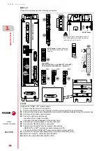
X4 connector
X4. Motor feedback
Is the connector for the motor feedback board that may come on modular
drives. It is a high density (HD) 26-pin sub-D type female connector.
Through it, the board receives the signals coming from the feedback de-
vice attached to the motor shaft.
The pinout of connector X4 depending on whether the motor feedback
board installed at the drive is a CAPMOTOR-1 or a CAPMOTOR-2 is:
The feedback of FAGOR motors use sinusoidal encoder, incremental TTL
encoder or resolver. Refer to the corresponding motor manual for the de-
tailed description of the pinout of the feedback devices that can go with
each motor family.
With CAPMOTOR-2, this connector admits signals:
Square TTL
1 Volt peak-to-peak sinusoidal (1 Vpp)
SSI
EnDat
with the following working frequencies:
1 MHz with square signals
500 kHz with sinusoidal signals
The input impedance for sinusoidal signals is 120
The characteristics of the signals are the same as the ones described in
the previous chapter for the incremental and absolute feedback devices.
See figures
,
F. H3/70
Connector X4. Feedback on the motor. CAPMOTOR-1 or CAPMOTOR-2.
NOTE.
To know whether your drive has a CAPMOTOR-2 installed,
check the label on the side of the drive and see if the last field of the
sales reference is a B. If not, it will have a CAPMOTOR-1.
COS
SIN
R1
REFSIN
R2
I0
S1
S4
REFCOS
R3
S2
+485
-485
TEMP
TEMP
+8VDC
+5VDC
GND(0)
CHASIS
COS / A+
SIN / B+
V-
N.C.
REFSIN / B-
U+ / C-
W+ / D-
V+
I0+ / DATA+
U- / C+
I0- / DATA-
W- / D+
N.C.
N.C.
REFCOS / A-
VSENSE-
N.C.
+485/CLK+/ALARM+
-485/CLK-/ALARM-
TEMP
TEMP
+8VDC
+5VDC
GND(0)
CHASIS
REFI0
V-
U- / C+
W- / D+
U+ / C-
W+ / D-
V+
CONNECTOR X4
X4. CAPMOTOR-1
X4. CAPMOTOR-2
Notes.
Do not select a drive with CAPMOTOR-2 when the motor feedback is
a resolver. They are incompatible. In this case, the drive must always
carry a CAPMOTOR-1.
Do not connect an SSI or EnDat feedback device to connector X4 of
the drive of a CAPMOTOR-1 motor feedback board. They are incom-
patible.
Front view of
the drive
Содержание DDS
Страница 1: ...DRIVE DDS Hardware manual Ref 1310...
Страница 6: ...I 6 DDS HARDWARE Ref 1310...
Страница 9: ......
Страница 10: ......
Страница 11: ......
Страница 12: ......
Страница 16: ...16 Ref 1310 DDS HARDWARE...
Страница 30: ...1 DESCRIPTION 30 Description DDS HARDWARE Ref 1310...
Страница 94: ...2 POWER SUPPLIES 94 Power supplies DDS HARDWARE Ref 1310...
Страница 188: ...3 DRIVE MODULES 188 Drive modules DDS HARDWARE Ref 1310...
Страница 204: ...4 AUXILIARY MODULES 204 Auxiliary modules DDS HARDWARE Ref 1310...
Страница 232: ...SELECTING CRITERIA 5 232 Selection criteria DDS HARDWARE Ref 1310...
Страница 266: ...7 CABLES 266 Cables DDS HARDWARE Ref 1310...
Страница 312: ...8 INSTALLATION 312 Installation DDS HARDWARE Ref 1310...
Страница 326: ...9 FUNCTIONAL SAFETY 326 Functional safety DDS HARDWARE Ref 1310...
Страница 354: ...10 CONNECTION DIAGRAMS 354 Connection diagrams DDS HARDWARE Ref 1310...
Страница 378: ...12 SALES REFERENCES 378 Sales references DDS HARDWARE Ref 1310...
Страница 384: ...13 COMPATIBILITY 384 Compatibility DDS HARDWARE Ref 1310...
Страница 385: ......