


Power supplies
POWER SUPPLIES
Re
gen
erative pow
er
su
ppli
es
2.
65
DDS
HARDWARE
Ref.1310
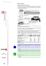
Module power-up
1.
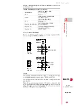
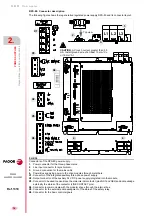
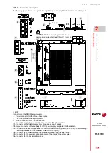
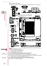
For the XPS-25 and XPS-65 power supplies:
Apply power to the Auxiliary Power Supply from mains through pins 2 and
3 of connector X3; These will power the control circuits of the power sup-
ply and provide 24 V DC at connectors X4, X5 and X6.
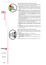
2.
The power supply checks the system status:
If the status is correct:
The
System OK
contact closes (pins 6 and 7) and it stays closed while
the control circuits are powered and no error comes up in any of the mod-
ules of the system.
The red FAULT indicator light blinks (it is not indicating an error because
there are no phases yet).
If the status is not correct:
The red FAULT indicator light is permanently on (not blinking).
3.
Apply power to the power supply:
Power is applied from mains through the power connectors on top of the
power supply.
The soft start begins.
The red FAULT indicator light turns off.
4.
green DC BUS ON light on:
After 4 seconds, the green DC BUS ON indicator light turns on meaning
that the power bus has the proper dc voltage.
If for any reason an error is activated at the power supply module or at
any drive module it supplies to, the system will act as follows:
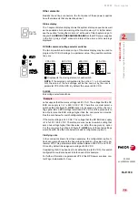
1.
The green indicator light DC BUS ON will turn off indicating that the
power supply will stop supplying voltage to the power bus.
2.
The red FAULT light will be on permanently.
With the Error RESET input (pin 1), it is possible to eliminate the errors at
the drives that are part of the system
- see chapter 14, resettable errors,
of the “man_dds_soft.pdf” manual - and it acts as follows:
Its state will be 0 V DC. Activating it with 24 V DC erases all the er-
rors stored in the memory of each drive of the system.
Should the cause of the error persist, the corresponding module will
show the same error again and it will be necessary to turn the unit back
on to eliminate the error if it is a serious error.
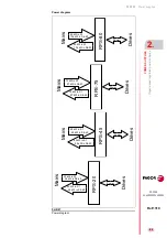
The System Speed Enable input (pin 5) is related to the Speed Enable in-
puts of the drive modules so the System Speed Enable activates/cancels
internally all the Speed Enable of the drives connected to the power supply
through the internal bus.
The state of the System Speed Enable is usually 24 V DC.
When removing the 24 V DC from the System Speed Enable pin is set
to 0 V DC, all the drive modules joined together by the same internal
bus will brake the motors that they control with the torque correspond-
ing to the active acceleration ramp and when stopped or when reach-
ing the time limit to stop, programmable according to parameter GP3
(see chapter 13 of the “man_dds_soft.pdf” manual), it cancels the mo-
tor torque.
The consumption of each input is between 4.5 and 7 mA.
DANGER.
When the DC BUS ON led turns off it may take about 4 min-
utes for the bus to discharge to a safe value (< 42 V DC) depending on
the number of drive modules that are connected.
Содержание DDS
Страница 1: ...DRIVE DDS Hardware manual Ref 1310...
Страница 6: ...I 6 DDS HARDWARE Ref 1310...
Страница 9: ......
Страница 10: ......
Страница 11: ......
Страница 12: ......
Страница 16: ...16 Ref 1310 DDS HARDWARE...
Страница 30: ...1 DESCRIPTION 30 Description DDS HARDWARE Ref 1310...
Страница 94: ...2 POWER SUPPLIES 94 Power supplies DDS HARDWARE Ref 1310...
Страница 188: ...3 DRIVE MODULES 188 Drive modules DDS HARDWARE Ref 1310...
Страница 204: ...4 AUXILIARY MODULES 204 Auxiliary modules DDS HARDWARE Ref 1310...
Страница 232: ...SELECTING CRITERIA 5 232 Selection criteria DDS HARDWARE Ref 1310...
Страница 266: ...7 CABLES 266 Cables DDS HARDWARE Ref 1310...
Страница 312: ...8 INSTALLATION 312 Installation DDS HARDWARE Ref 1310...
Страница 326: ...9 FUNCTIONAL SAFETY 326 Functional safety DDS HARDWARE Ref 1310...
Страница 354: ...10 CONNECTION DIAGRAMS 354 Connection diagrams DDS HARDWARE Ref 1310...
Страница 378: ...12 SALES REFERENCES 378 Sales references DDS HARDWARE Ref 1310...
Страница 384: ...13 COMPATIBILITY 384 Compatibility DDS HARDWARE Ref 1310...
Страница 385: ......