background image

Mini-Mag Service Manual V1.0 

12

12-7

ELECTRICAL SYSTEM

5

5

4

4

3

3

2

2

1

1

D

D

C

C

B

B

A

A

NEGATIVE BATTERY CABLE

POSITIVE BATTERY CABLE

BLACK #72

ORANGE #71

ORANGE #71

BLACK #72

10 Ga. BLACK

10 Ga. BLACK

10 Ga. BLACK

10 Ga. RED

10 Ga. RED

10 Ga. RED

WHITE #131

WHITE #131

WHITE #131

PINK #130

PINK #130

PINK #130

10 Ga. BLACK

10 Ga. BLACK

10 Ga. BLACK

10 Ga. RED

10 Ga. RED

RED #183

RED #183

RED #183

BLACK #184

BLACK #184

BLACK #184

TO CENTRAL COMMAND

TO CENTRAL COMMAND

TO 12 PIN MOLEX CONNECTOR

TO 12 PIN MOLEX CONNECTOR

TO GROUND STUD IN CENTRAL COMMAND

TO BRUSH MOTOR CIRCUIT BREAKER

TO 12 PIN MOLEX CONNECTOR

TO 12 PIN MOLEX CONNECTOR

TO GROUND STUD IN CENTRAL COMMAND

TO VACUUM MOTOR CIRCUIT BREAKER

TO 12 PIN MOLEX CONNECTOR

TO 12 PIN MOLEX CONNECTOR

Title

Size

Document Number

Rev

Date:

Sheet

of

000-000

1.0

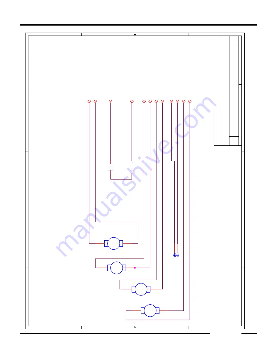
MiniMAG - Brush Assist - Body Wiring

A

1

1

Tuesday, December 05, 2006

Title

Size

Document Number

Rev

Date:

Sheet

of

000-000

1.0

MiniMAG - Brush Assist - Body Wiring

A

1

1

Tuesday, December 05, 2006

Title

Size

Document Number

Rev

Date:

Sheet

of

000-000

1.0

MiniMAG - Brush Assist - Body Wiring

A

1

1

Tuesday, December 05, 2006

BT3

BATTERY 12 VOLT

BT3

BATTERY 12 VOLT

M1

-

+

MOTOR, VACUUM

M1

-

+

MOTOR, VACUUM

1

2

BT4

BATTERY 12 VOLT

BT4

BATTERY 12 VOLT

M4

-

+

MG4

MOTOR, BRUSH DRIVE

M4

-

+

MG4

MOTOR, BRUSH DRIVE

1

2

M2

-

+

MOTOR, BRUSH ACCTUATOR

M2

-

+

MOTOR, BRUSH ACCTUATOR

1

2

SOLUTION, SOLENOIDSOLUTION, SOLENOID

1 2

M3

-

+

MOTOR, SPRAY JET

M3

-

+

MOTOR, SPRAY JET

1

2

Содержание MINI-MAG SERIES

Страница 1: ...SERVICE MANUAL R P S Corporation Phone 1 800 634 4060 P O Box 241 Fax 1 866 632 6961 Racine Wisconsin Version 1 0 MINI MAG SERIES ...

Страница 2: ......

Страница 3: ...easy reference When properly used it will meet the needs of technicians and equipment owners No part of this publication may be reproduced stored in any retrieval system or trans mitted on any form or by any means including but not limited to electronic mechanical photocopying recording or otherwise with out the prior written permission of the R P S Corporation This includes all text illustrations...

Страница 4: ...signed for the purpose Accordingly anyone who intends to use a replacement part service procedure or tool which is not recommended by the equipment manufacturer must determine that neither his safety nor the safe operation of the equipment will be jeopardized by the replacement part service procedure or tool selected It is important to note that this manual contains various cautions and notices th...

Страница 5: ...d straight up or down the ramp Never drive across the incline Do not back down or turn on ramps Always use the charger provided by the manufacturer to charge the machine It is an automatic charger specifically designed to charge at the appropriate rate If you must use a different charger disconnect the batteries from the machine as this will protect the on board electronics Understand the dynamic b...

Страница 6: ...floors only and in an indoor environment with the recommended pads and brushes with approved cleaning solutions DO NOT OPERATE THE UNIT UNLESS TRAINED AND AUTHORIZED UNLESS OPERATOR MANUAL IS READ AND UNDERSTOOD IF UNIT IS NOT IN PROPER OPERATING CONDITION WHEN OPERATING UNIT WEAR PROPER PROTECTIVE EQUIPMENT REMOVE LOOSE OBJECTS FROM THE FLOOR THAT MAY BE PROJECTED FROM THE REVOLVING BRUSHES DO NOT...

Страница 7: ...TE TOW BAR 3 3 SIDEWAYS MOVEMENT 3 3 UP DOWN MOVEMENT 3 3 ORDERING BLADES 3 4 REPLACING BLADES 3 4 SQUEEGEE BLADES 3 3 SQUEEGEE ADJUSTMENT 3 5 PITCH ADJUSTMENT KNOB 3 5 SQUEEGEE ADJUSTMENT EXAMPLES 3 6 SQUEEGEE LIFT SYSTEM 4 1 TO OPERATE 4 1 SQUEEGEE LIFT ADJUSTMENTS 4 1 SQUEEGEE LIFT ELECTRICAL CIRCUIT 4 1 BRUSH DRIVE 4 1 TRACTION DRIVE 4 2 RECOVERY SYSTEM 5 1 RECOVERY LID 5 1 DRAIN SAVER 5 1 VAC...

Страница 8: ... 1 BRUSH DRIVE ELECTRICAL CIRCUITS 7 2 BRUSH ASSIST MODELS 7 2 SETTING BRUSH PRESSURE 7 2 BRUSH ASSIST 7 2 TRACTION DRIVE MODELS WITH CENTRAL COMMAND II 7 3 INSTALLING REMOVING BRUSHES 7 4 DISC MACHINES 7 4 CYLINDRICAL DECK 7 4 BRUSH ASSIST SYSTEM 7 5 BRUSH ASSIST 7 5 BRUSH ASSIST STRENGTH 7 5 BRUSH LIFT SYSTEM 8 1 BRUSH ASSIST 8 1 BRUSH LIFT ELECTRICAL CIRCUIT 8 1 DOWN PRESSURE ADJUSTMENT 8 2 TRA...

Страница 9: ...S 11 1 SAFE CHARGING 11 1 HANDLING BATTERY ACID 11 2 WATER 11 2 BATTERY TERMINAL TYPES 11 2 COMBINATION TERMINAL 11 3 STUD TERMINAL 11 3 TAPERED TOP TERMINAL S A E POST 11 2 THE L TERMINAL 11 3 BATTERY SYSTEM 11 4 BATTERY MAINTENANCE CARE 11 4 LEAD ACID BATTERIES TRADITIONAL 11 4 LEAD ACID BATTERIES MAINTENANCE FREE 11 4 GEL CELL BATTERIES 11 4 BATTERY CABLES TERMINALS 11 5 BATTERY TESTING 11 5 HY...

Страница 10: ... 1 CONTROLLER OVERVIEW 13 1 INPUTS 13 1 OUTPUTS 13 1 CONTINUITY TESTING 13 1 PULSE WIDTH MODULATION 13 1 SOFT START 13 2 CONNECTIONS 13 2 AMP TERMINALS 13 2 BINDING POST TERMINALS 13 2 MOLEX MINI FIT JR 13 2 TIMED CIRCUITS 13 2 BATTERY METER 13 2 DOWN PRESSURE CONTROL 13 2 LCD DISPLAY 13 3 SCREEN 1 13 3 SCREEN 2 13 3 SCREEN 3 13 4 SCREEN 4 13 4 ON BOARD DIAGNOSTICS 13 5 DIAGNOSING THE CONTROL SYST...

Страница 11: ...F 2 13 21 VACUUM MOTOR DIAGNOSTICS 1 OF 2 13 22 VACUUM MOTOR DIAGNOSTICS 2 OF 2 13 23 TRACTION DRIVE W CCII 13 24 BRUSH DECK ACTUATOR DIAGNOSIS 1 OF 1 13 24 BRUSH MOTOR DUAL DIAGNOSIS 1 OF 1 13 26 BRUSH MOTOR SINGLE DIAGNOSIS 1 OF 1 13 25 BRUSH PRESSURE SWITCH DIAGNOSIS 1 OF 2 13 27 BRUSH PRESSURE SWITCH DIAGNOSIS 1 OF 2 13 28 BRUSH PRESSURE SWITCH DIAGNOSIS 2 OF 2 13 29 BRUSH SWITCH DIAGNOSIS 1 O...

Страница 12: ...Mini Mag Service Manual V1 0 TOC toc 1 6 TABLE OF CONTENTS BLANK THIS PAGE WAS INTENTIONALLY LEFT BLANK ...

Страница 13: ... wear Failure to inspect on regular intervals can result in motor dam age that is not covered under warranty LUBRICATION The machine requires periodic lubrication on each grease fitting on the machine and oiling of some pivot points and threads Once a month is generally acceptable unless the ma chine is used in a severe duty application The grease fittings are located on Rear casters The following p...

Страница 14: ...Mini Mag Service Manual V1 0 1 1 2 MAINTENANCE ...

Страница 15: ...Mini Mag Service Manual V1 0 1 1 3 MAINTENANCE ...

Страница 16: ...Mini Mag Service Manual V1 0 1 1 4 MAINTENANCE BLANK THIS PAGE WAS INTENTIONALLY LEFT BLANK ...

Страница 17: ...TCH OPTIONAL 7 CIRCUIT BREAKER 2 AMP 8 CIRCUIT BREAKER 25 AMP 9 CIRCUIT BREAKER 40 AMP 10 SPRAY JET SWITCH BLUE 11 FUTURE USE 12 CHARGER PORT 13 HANDLE BAR 14 FORWARD REVERSE SWITCH RED 15 SOLUTION FLOW CONTROL KNOB 16 LCD SCREEN 17 PAGE BUTTON 18 SCRUB DECK SWITCH 19 DOWN PRESSURE TOGGLE SWITCH 20 WARNING PLATE 21 WARNING PLATE 22 SERIAL NUMBER PLATE 23 SPEED CONTROL KNOB ...

Страница 18: ...Mini Mag Service Manual V1 0 2 2 2 MACHINE INTRODUCTION 24 TRACTION DRIVE 25 SOLUTION FLOW VALVE 26 SOLUTION FILTER 27 WALL ROLLERS 28 PAD ASSIST DRIVE ADJUSTMENT KNOB ...

Страница 19: ...ER 31 VAC SCREEN 32 CASTER 33 MAIN TIRE 34 JAWS 35 TANK IN A TANK 36 SOLUTION FILL ID 37 RECOVERY LID 38 CLEAR COVER 39 CONTROL PANEL 40 SOLUTION LEVEL DRAIN TUBE 41 VACUUM HOSE 42 SQUEEGEE BLADE 43 SQUEEGEE PITCH ADJUSTMENT 44 ON BOARD BATTERY CHARGER 45 RECOVERY DRAIN HOSE 46 TANK LATCH BODY ...

Страница 20: ...s through information on the LCD Screen 18 SCRUB DECK SWITCH Raises and lower the scrub deck 19 DOWN PRESSURE TOGGLE SWITCH Controls the down pressure placed on the scrub deck 20 WARNING PLATE Relays precautions regarding the machine and or its operation 21 WARNING PLATE Relays precautions regarding the machine and or its operation 22 SERIAL NUMBER PLATE Machine identification 23 SPEED CONTROL KNOB...

Страница 21: ...lution in the tank and act as a drain 41 VACUUM HOSE Provides vacuum path from the squeegee to the recovery tank 42 SQUEEGEE BLADE Recovers dirty water from the floor and directs it into the vacuum hose 43 SQUEEGEE PITCH ADJUSTMENT Provides adjustment of the squeegee pitch forward and rearward 44 ON BOARD BATTERY CHARGER Recharges batteries 45 RECOVERY DRAIN HOSE Allows for controlled draining of r...

Страница 22: ...Mini Mag Service Manual V1 0 2 2 6 MACHINE INTRODUCTION BLANK THIS PAGE WAS INTENTIONALLY LEFT BLANK ...

Страница 23: ...ecovery system also must be operating properly for the squeegee to perform well SQUEEGEE SYSTEM COMPONENTS The squeegee tool with replaceable rollers blades A suspension that mounts the squeegee to the machine and allows the squeegee to move up and down with variations in the floor and pivot in turns A lift system that allows the operator to raise the squeegee off the floor The machine has a manual ...

Страница 24: ...proper spacing between the triangle plate and the trail Arm E SQUEEGEE TRIANGLE PLATE The squeegee is mounted to the triangle plate and ties it to the trail arm F SPRING Supplies pressure between the Triangle plate and the trail arm Helps hold the adjust ment The squeegee will not operate without this spring G PITCH ADJUSTMENT KNOB The knob used to pitch the squeegee frontward or backwards The squ...

Страница 25: ...ee suspension does not move up and down properly check the bolts and the Oilite bushings at the pivot point If the bolts are too tight may have been tightened by customer by mistake or the bushings are dried out or worn the squeegee will not be able to float properly SIDEWAYS MOVEMENT The squeegee must be allowed to move from side to side so that if it hits an obstacle it can move out of the way If...

Страница 26: ...p of the squeegee body and order blades the corresponding blade size 32 35 or 38 inches 2 Choose the appropriate material Gum rubber These blades are tan in color and best for most applications including irregular floors They wear out quickly on rough floors however and do not tolerate oil other petroleum products or heavy citrus cleaners The kit number suffix for gum rubber is G Example 28 770 G Lin...

Страница 27: ...rying to achieve is to have the squeegee PERFECTLY parallel with the floor From that point rock ing the squeegee forward about one half degree of pitch will reduce air leak Rocking the squeegee backwards about one half degree will increase the air leak PITCH ADJUSTMENT KNOB The triangular shaped plate that the squeegee bolts to is adjustable for a slight amount of up down pitch As you turn the knob...

Страница 28: ...Mini Mag Service Manual V1 0 3 3 6 SQUEEGEE SYSTEM SQUEEGEE ADJUSTMENT EXAMPLES ...

Страница 29: ... squeegee blade kit The trailing wheels should be changed when the blades are changed or immediately if they become damaged Our squeegee trailing wheel system is theoretically not adjustable meaning that it is not intended for end users to adjust it If you have good wheels of the correct diameter on the squeegee and they contact the floor incorrectly then observe the space between the wheels and a ...

Страница 30: ...Mini Mag Service Manual V1 0 3 3 8 SQUEEGEE SYSTEM ...

Страница 31: ...dels SQUEEGEE LIFT ADJUSTMENTS There are no provisions for adjustment of the squeegee lift If the squeegee is not raising and lowering properly it is due to a bent or worn part or parts Inspect the lift assembly and other related systems for bent or worn parts and replace as necessary SQUEEGEE LIFT ELECTRICAL CIRCUIT BRUSH DRIVE Although the squeegee lift is a manual lift there is an electrical ci...

Страница 32: ... controller telling it that the squeegee is down on the floor When it sees this signal it turns on the vacuum motor When the squeegee lever is moved to lift the squeegee up the switch in no longer depressed and the signal going to the controller is interrupted When the controller no longer sees the signal for the vacuum motor it runs the vacuum motor for 21 additional seconds to clear any excess wa...

Страница 33: ...aver and out through the vacuum motor The recovery tank is equipped with a clear lid that allows the operator to observe the conditions inside the recovery tank as well as the recovery water level inside Inside the recovery tank there are 4 major components The recovery lid drain saver vacuum float and the water baffle RECOVERY LID The recovery lid is made from 10 gaugee stainless steel with a clear...

Страница 34: ... lid The baffle adds rigidity to the tank walls and lessens the sloshing of the water inside the recovery tank VACUUM FLOAT The vacuum float assembly is located inside the recovery tank and is accessed by opening the re covery tank lid The float assembly stops the flow of air to the vacuum motor in the event that the recovery tank is filled to capacity DRAIN HOSE To drain the recovery system we have a ...

Страница 35: ...lable it is advised to replace the entire motor as all the motor parts have about the same life and repairs of the motor unit are usually cost prohibitive VACUUM SAVER The MiniMAG is equipped with a vacuum saver demisting chamber that prevents moisture that gets through the recovery system from reaching the vacuum motor The vacuum saver is a chamber that allows moist air to condense and has an aut...

Страница 36: ...nd float ball cage clean YES Verify customer complaint Is there a problem YES Empty tank and clean Drain Saver and float ball cage NO Retest the machine Are the gaskets the clear recovery lid and the stainless recovery tank door in good condition YES Repair or replace parts as needed Retest machine Did this remedy the problem NO YES GOTO PAGE 2 Turn on vacuum switch YES NO NO Does the vacuum motor...

Страница 37: ...customer on proper machine maintenance Check vacuum lift at the end of the squeegee hose NO YES YES NO Do you have good vacuum at the squeegee hose Call the factory YES NO Remove squeegee and see if it is clogged YES Is the squeegee adjusted properly Adjust squeegee and retest machine See squeegee section for assistance Did this remedy the problem NO NO FROM PAGE 1 Bill customer See Next Page Mini...

Страница 38: ...od vacuum Call the factory Unbolt the vacuum motor from the tank Test the vacuum directy at the vacuum motor Check the motor saver for cracks make sure all the gaskets are in good condition and check the duck bill Is everything is good order Call the factory Repair as necessary and then retest machine Did this remedy the problem Bill the customer YES NO YES NO YES NO Do you have good vacuum NO YES...

Страница 39: ...n that is called for the longer the length of the power pulse When the potentiometer is turned to the MAX solution setting the valve receives constant power when the scrub deck is running When the potentiometer is set to the MIN position the solution solenoid valve receives no power even when the brushes are running FILTRATION The solution runs through an in line filter with a screen and a bowl att...

Страница 40: ...ler produces a high 5 volt and a low 0 volt signal that is sent to the potentiometer the potentiometer outputs a varied voltage from 0 to 5 volts The controller also sends a 5 volt signal to the scrub switch When the scrub switch is turned on this 5 volt signal is sent to the scrub input on the controller and the controller then looks at the input from the solution potentiometer When either handle...

Страница 41: ...ove the clear part of the plastic filter housing Remove screen and clean Replace screen and clear part of filter housing DRAINING SOLUTION TANK Detach the solution drain sight gauge hose from the upper barb and lower into a suitable drain or receptacle When the solution has emptied reattach the hose to the upper barb SOLUTION DRAIN SIGHT GAUGE SOLUTION FILTER ...

Страница 42: ...Magnum Service Manual V1 0 6 6 4 SOLUTION SYSTEM BLANK THIS PAGE WAS INTENTIONALLY LEFT BLANK ...

Страница 43: ...ISC The disc brush drive system consists of the controller 1 or 2 brush drive motors 1 or 2 brush driver hubs and 1 or 2 scrub brushes or pad holders The drive hub is a gimbaled design that helps compensate for irregularities of the floor Only original factory equipment brushes should be used on this machine or premature scrub motor failure may occur Will Fit brushes are usually not concentric and ...

Страница 44: ...deck switch handle bar buttons controller and brush deck motor s When the brush deck switch is turned on and the handle bar button is depressed the controller sends power to the brush The controller then watches the amperage draw on the scrub deck motor s and regulates the brush deck pressure to keep the motors operating at a consistent amp draw thus maintain ing a consistent deck pressure SETTING...

Страница 45: ...is programmed with an amp value for each of 5 brush pressure settings When the scrub deck starts the controller calculates the amp draw of the motors and compares it to the amp value of the current brush pressure set ting If the motors are not drawing enough amps the controller lowers the brush deck to increase the brush pressure on the ground and therefore raise the amp draw of the motors If the ...

Страница 46: ... again If the brushes still can not be removed due to lack of space the actuator or linkage must be adjusted To install a brush reverse the procedure CYLINDRICAL DECK With the brush deck raised remove the side access door from the scrub deck Grasp the scrub brush and pull and it will slide off the brush driver and out from under the scrub deck To install brushes align brush with the brush drive an...

Страница 47: ... propel the machine forward There is a knob on the left side of the scrub deck that allows the operator to adjust the amount of propulsion The knob applies pressure to a wheel that runs on the top of the scrub brush or pad holder applying pressure to one side of the brush or pad holder causing the brush or holder to pull the machine forward BRUSH ASSIST STRENGTH First adjust the brush deck pressur...

Страница 48: ...Mini Mag Service Manual V1 0 7 7 6 BRUSH DRIVE SYSTEM BLANK THIS PAGE WAS INTENTIONALLY LEFT BLANK ...

Страница 49: ...r on the back of the control panel BRUSH LIFT ELECTRICAL CIRCUIT The negative side of the battery is connected to the brush deck lift switch Positive power from the main power switch is fed to the brush deck lift switch The switch is then wired to the brush deck actuator with a 2 amp circuit breaker in line on the positive side When the switch is depressed to lower the brush current is sent to the...

Страница 50: ...eck The amount of down pressure is monitored using the brush pressure gauge located on the lower right corner of the control panel This gauge should always be in the green when operating If the gauge goes into the red there is too much brush pressure being applied The brush deck is raised and lowered using the rocker switch on the top of the control panel ...

Страница 51: ...ogramed into the controller When the throttle of the machine is released the scrub brushes raise up off the floor for 2 seconds This is called raise time The purpose of this is so the scrub brushes start up under reduced load which leads to much longer motor life Raise time can be modified and is set through programing If scrubbing begins again the brushes drop back down to the floor and the controll...

Страница 52: ...strap stops it After the adjustments have been made tip up the body secure the two soft latches and test the machine BRUSH LIFT ACTUATOR The actuator must be able to extend enough to lower the brush head down so that it can reach slight dips in the floor If the head can not do this the actuator may not be extending enough The distance the actuator extends is controlled by a limit switch that is hou...

Страница 53: ... suspension arm LINKAGE ADJUSTMENT If the brush deck is out of adjustment and it can not be remedied with the limit switch ad justment there is a provision for adjusting the linkage At the top of the brush deck lift linkage there is a bolt that is secured with a jamb nut This bolt is used to increase or de crease the raised height of the deck If too much adjustment is made to this screw to lift th...

Страница 54: ...Mini Mag Service Manual V1 0 8 8 6 BRUSH LIFT SYSTEM BLANK THIS PAGE WAS INTENTIONALLY LEFT BLANK ...

Страница 55: ...l instruct ing it to move The controller then energizes the drive motor to propel the machine in reverse Both the forward and reverse speeds are regulated by the potentiometer located on the control panel The controller has internal protection for the drive motor It will slow the machine down if the traction motor draws too many amps for more than 60 seconds If the overload continues the controlle...

Страница 56: ...Mini Mag Service Manual V1 0 9 9 2 TRACTION DRIVE SYSTEM BLANK THIS PAGE WAS INTENTIONALLY LEFT BLANK ...

Страница 57: ...o the new chassis and installing the tank last on the new chassis TIRES There are 5 different tire options for the Magnum series of scrubbers We offer pneumatic tires as a standard tire grey tires for non marking applications Both the black and grey tires are available foam filled but come with a 90 day warranty There is also a HD tire op tion which is a solid tire CASTERS There are 2 different typ...

Страница 58: ...Mini Mag Service Manual V1 0 10 10 2 CHASSIS SYSTEM BLANK THIS PAGE WAS INTENTIONALLY LEFT BLANK ...

Страница 59: ... for the charger be ing used In addition to the manufacturer s instructions these general precautions should be followed Always wear proper eye face and hand protection Always charge batteries in a well ventilated area Keep vents tight and level Turn the charger and timer OFF before connecting the leads to the battery to avoid dan gerous sparks Never try to charge a visibly damaged or frozen batte...

Страница 60: ...ectrolyte However any water that is safe to drink with the exception of mineral or flavored waters is safe to use in a battery Do not use water with a high mineral content Avoid using metal containers to store acid or water The metal impurities in the water will diminish the performance of the battery Liquids besides water such as vinegar anti freeze salt water and alcohol or harmful acids such as ...

Страница 61: ...ide there is a tapered top terminal with a stud terminal right next to it In the stacked configuration the stain less steel stud is embedded into the taper top terminal The combination terminals make it possible to use the battery with a variety of equipment without having to change the cables on it CAUTION The stacked type combination battery terminals are very tall in compari son to all other con...

Страница 62: ...ust above the top of the plates When adding water ALWAYS use distilled water Tap water contains things like minerals and chlorine that is detrimental to a battery Bat teries should be charged each time the machine is used for any significant time Batteries should never be discharged more than 80 of their capacity The battery gauge is to alert you when it is time to stop using the machine and rechar...

Страница 63: ...f the machine Neglected batteries will wear out much faster than well maintained batteries but give you similar symptoms when they do fail The proper way to check a battery pack s condition is with a battery discharge unit To use the discharge unit make sure the batteries are maintained properly and fully charged Attach the discharge unit to the machines battery pack and turn the machine on Record...

Страница 64: ...n the float The lower the float sinks in the electrolyte the lower its specific gravity The proper way to read a hydrometer is to dray electrolyte into the body of the hydrometer while holding it ver tically so the float is not rubbing on the side of it Draw an amount of acid into the body so the that with the bulb fully expended the float will be lifted free not touching either side the top or the bot...

Страница 65: ...y can be tested individually Using a battery load tester test each battery at either the fixed load of the tester or a 120 amp of load on a variable tester The batteries should be able to maintain a voltage of 10 8 volts or greater for 15 seconds on 12 volt batteries and 4 9 volts or greater for 15 seconds on a 6 volt battery If they can not maintain their voltage while under load they are bad Load...

Страница 66: ...the directions on the can of protectant ex actly to prevent terminal or cable failure BATTERY CHARGER The standard charger supplied with the MiniMAG is an on board fully automatic charger To operate the charger all that needs to be done is plug in the charger cord into a wall outlet of the proper voltage The charger will run until the batteries are fully charged and then automatically shut off It ...

Страница 67: ...r can be instantaneously destroyed RELAYS The MiniMAG series uses only one relay This relay is used to power the positive buss bar and isolate it from the controller There are relays internally mounted in the controller but these are not serviceable The relay we use is a 24V 15A Hella relay This relay is energized by the key switch and is relays power to the positive buss bars MOTORS The motors th...

Страница 68: ...hem STANDARD CRIMP ON TERMINALS The standard crimp on terminals we use on our equipment should be crimped with a posi tive stop ratchet type crimpers The correct color coded terminal must be installed for the machine to operate properly with it s original integrity It is important to use the Ratchet style crimpers to assure the connector is installed properly The ratchet style crimpers regulates t...

Страница 69: ...s needed a wire end kit is available that is field installable This kit is available through the parts department ANDERSON BATTERY CONNECTORS Anderson connectors are crimped by a hydraulic crimping machine at the factory This is not practical in the field We recommend using a manual staking tool and then soldering the terminal to assure a good solid connection REMOVAL TOOL MOLEX MINI FIT JR CRIMPING...

Страница 70: ...ev Date Sheet of 000 000 1 0 MiniMAG Traction Drive Central Command C 1 1 Tuesday December 05 2006 Title Size Document Number Rev Date Sheet of 000 000 1 0 MiniMAG Traction Drive Central Command C 1 1 Tuesday December 05 2006 Title Size Document Number Rev Date Sheet of 000 000 1 0 MiniMAG Traction Drive Central Command C 1 1 Tuesday December 05 2006 MOLEX 20 PIN MOLEX 20 PIN 10 9 8 7 6 5 4 3 2 1 ...

Страница 71: ...LLER TO 12 PIN MOLEX CONNECTOR TO 12 PIN MOLEX CONNECTOR TO CONTROLLER TO CONTROLLER Title Size Document Number Rev Date Sheet of 000 000 1 0 MiniMAG Traction Drive Body Wiring A 1 1 Tuesday December 05 2006 Title Size Document Number Rev Date Sheet of 000 000 1 0 MiniMAG Traction Drive Body Wiring A 1 1 Tuesday December 05 2006 Title Size Document Number Rev Date Sheet of 000 000 1 0 MiniMAG Trac...

Страница 72: ...ERY Title Size Document Number Rev Date Sheet of 000 000 1 0 MiniMAG Brush Assist Central Comand B 1 1 Tuesday December 05 2006 Title Size Document Number Rev Date Sheet of 000 000 1 0 MiniMAG Brush Assist Central Comand B 1 1 Tuesday December 05 2006 Title Size Document Number Rev Date Sheet of 000 000 1 0 MiniMAG Brush Assist Central Comand B 1 1 Tuesday December 05 2006 CONNECTOR COMMAND MOLEX ...

Страница 73: ...OLEX CONNECTOR TO GROUND STUD IN CENTRAL COMMAND TO VACUUM MOTOR CIRCUIT BREAKER TO 12 PIN MOLEX CONNECTOR TO 12 PIN MOLEX CONNECTOR Title Size Document Number Rev Date Sheet of 000 000 1 0 MiniMAG Brush Assist Body Wiring A 1 1 Tuesday December 05 2006 Title Size Document Number Rev Date Sheet of 000 000 1 0 MiniMAG Brush Assist Body Wiring A 1 1 Tuesday December 05 2006 Title Size Document Numbe...

Страница 74: ...Mini Mag Service Manual V1 0 12 12 8 ELECTRICAL SYSTEM U Schematics Wire Numbering protocol pdf 1 of 5 2 17 2006 9 29 AM ...

Страница 75: ...Mini Mag Service Manual V1 0 12 12 9 ELECTRICAL SYSTEM USED ON ONLY 390 420 and 430 U Schematics Wire Numbering protocol pdf 2 of 5 2 17 2006 9 29 AM ...

Страница 76: ...Mini Mag Service Manual V1 0 12 12 10 ELECTRICAL SYSTEM U Schematics Wire Numbering protocol pdf 3 of 5 2 17 2006 9 29 AM ...

Страница 77: ...Mini Mag Service Manual V1 0 12 12 11 ELECTRICAL SYSTEM U Schematics Wire Numbering protocol pdf 4 of 5 2 17 2006 9 29 AM ...

Страница 78: ...Mini Mag Service Manual V1 0 12 12 12 ELECTRICAL SYSTEM BLANK THIS PAGE WAS INTENTIONALLY LEFT BLANK ...

Страница 79: ... switches The tri state logic is comprised of low medium and high voltages The inputs have the mid voltage present at them until they are either drawn low or high by a switch OUTPUTS The controller has a number of outputs and each one of them is electronically protected from overload In the event of an overload the machine is shut down by the controller and a diagnostic trouble code is displayed o...

Страница 80: ...ng post type TIMED CIRCUITS The controller has the capability to control a circuit with a certain amount of logic We can customize the operation of a component beyond the simple on off operation Timers are used for our vacuum motors and our squeegee actuators to make the machine operation more user friendly The timer settings are changed through the controller programming BATTERY METER The battery...

Страница 81: ...he reverse switch were activated when the machine was powered on Make sure no buttons or switches are depressed and cycle the power to the machine 1 BATTERY METER 2 BRUSHES RUNNING 3 WATER OPERATING 4 BRUSH PRESSURE GAUGE 5 VACUUM MOTOR OPERATING 6 HIGH THROTTLE SCREEN 2 To access screen 2 push the green page button on the con trol panel once 7 KEY SWITCH HOUR METER This hour meter represents the ...

Страница 82: ... on the machine 11 TRACTION HOURS The hour total listed here indicates the total number of hours the traction drive has been oper ated on the machine 12 KEY SWITCH HOUR METER This hour meter rep resents the total number of hours the machine has been powered on This does not mean however that the machine has been used this long just that it has had the power on for the time indicated SCREEN 4 This ...

Страница 83: ...e control system unless otherwise specified you will al ways set your meter to the DC volts scale and connect your negative test lead to the negative battery cable or buss bar When measuring for amp draw you will always measure around ONLY 1 wire OR going to the device in question Place the meter clamp on the wire with power off to the device Zero out the meter and then power up the device and take...

Страница 84: ...o a 5K potentiometer on each of the outside terminals The voltage is summed by the potentiometer and the summed voltage is sent out the center terminal of the potentiometer to the input terminal on the controller As the potentiometer is rotated the center wiper contact inside increases or decreases it s distance from the high reference signal creating a sweeping voltage from about 0 0 volts to 5 1...

Страница 85: ...rameter we could make the brushes raise up when the machine went in reverse without having the operator manipulate a switch In order to change the parameters in a controller a T 194 programing kit is necessary With a laptop computer and the programming kit access can be gained to the parameters of the machine and they can be modified to make the machine react differ ently The controller has 135 par...

Страница 86: ...ries following appropriate procedures and then charge for 2 full cycles Re test the machine NO Is the electrolyte clear or dirty cloudy The batteries are damaged Replace the batteries DIRTY YES Are the plates inside the battery straight or warped The batteries are damaged Replace the batteries WARPED CLEAR With a graduated float type hydrometer measure the specific gravity of each cell of each bat...

Страница 87: ...ENCY STOP SWITCH ASSEMBLY NO NO NO YES Disconnect the 6 wire connector going to the LCD display from the controller With an ohm meter measure the resistance between the two terminals on the back of the e stop switch that the wires are connected to With the button popped up you should have 0 2 ohms or less of resistance Do you have 0 2 ohms or less of resistance NO YES Leave the 6 wire connector fo...

Страница 88: ...Saver and float ball cage clean YES Verify customer complaint Is there a problem YES Empty tank and clean Drain Saver and float ball cage NO Retest the machine Are the gaskets the clear recovery lid and the stainless recovery tank door in good condition YES Repair or replace parts as needed Retest machine Did this remedy the problem NO YES GOTO PAGE 2 Turn on vacuum switch YES NO NO Does the vacuu...

Страница 89: ...struct customer on proper machine maintenance Check vacuum lift at the end of the squeegee hose NO YES YES NO Do you have good vacuum at the squeegee hose Call the factory YES NO Remove squeegee and see if it is clogged YES Is the squeegee adjusted properly Adjust squeegee and retest machine See squeegee section for assistance Did this remedy the problem NO NO FROM PAGE 1 Bill customer See Next Pa...

Страница 90: ...have good vacuum Call the factory Unbolt the vacuum motor from the tank Test the vacuum directy at the vacuum motor Check the motor saver for cracks make sure all the gaskets are in good condition and check the duck bill Is everything is good order Call the factory Repair as necessary and then retest machine Did this remedy the problem Bill the customer YES NO YES NO YES NO Do you have good vacuum...

Страница 91: ...tion tank and re test the machine YES NO Disconnect both connectors to the Spray Jet motor and measure for voltage across the two terminals on the harness Is there battery voltage there YES YES NO YES NO Turn the spray jet pump off and remove the nozzle from the end of the hose Turn the spray jet on again Does the water flow well with good pressure Replace the Spray Jet pump Replace the nozzle YES...

Страница 92: ...h of the leads NO Was there power at either of the leads on the switch YES With a a voltmeter set to the DC scale measure the voltage from the positive to the negative buss bar with the Machine turned on Was there battery voltage across the buss bars NO See BUSS RELAY section Repair wiring to between the spray jet switch and the positive buss bar YES Call the factory YES With a voltmeter set to th...

Страница 93: ...e assist Reduce the amount of assist by rotating the assist knob counter clockwise 1 2 turn then re test machine TOO MUCH NO Check condtion of pad driver and scrubbing pad or brush TO LITTLE Is the pad pad driver or brush in good condition Replace items as needed and re test the machine NO Increase the amount of assist by rotating the assist knob clockwise 1 2 turn then re test machine YES YES Min...

Страница 94: ... battery voltage Advise customer on proper machine operation YES NO NO NO YES Is the power indicator lit on the control panel YES YES Check for power into the main power switch Is there power in NO NO YES NO YES Repair a break in the wiring between the main power switch and the wire to the actuator switch Repair break in the wiring between the buss and the the actuator switch NO GO TO PAGE 2 YES Y...

Страница 95: ...d backward and observe you meter readings Did you have battery voltage in both directions when you actuated the switch Did you have voltage in either direction Check continuity from the pink and white wires at the actuator to the actuator switch Do they both have good continuity Replace the actuator Replace the brush deck switch FROM PAGE 1 YES NO YES YES NO Find and repair break in wiring NO Mini...

Страница 96: ...tch NO Is the battery gauge in the green zone Charge Batteries Is the actuator circuit breaker tripped Reset breaker and test for proper operation NO YES YES NO YES YES NO Press the green handle bar button while touching the side of the brush motor relay You should feel the relay click when you depress the button Does the relay click GO TO PAGE 2 A NO Check for and power at the brush motor when th...

Страница 97: ...e going to the coil circuit on the brush relay when the green handle bar button is depressed FROM PAGE 1 B Check for battery voltage on the black wire to the brush relay coil circuit Is there battery voltage Repair the wiring and retest the machine YES NO Replace the brush relay Retest the machine YES Repair the wiring from the buss to the brush motor relay NO Check for battery voltage on the othe...

Страница 98: ...h water NO YES Is the solution screen clogged Solution tank outlet is clogged Clean out tank and remove foreign material from water outlet NO YES Clean solution screen and flush out the solution tank YES Is the water switch turned on Turn on the water switch NO YES NO NO Advise customer on proper machine operation YES See Next Page Is the ball valve at the brush deck open YES NO Open the ball valv...

Страница 99: ...NO Does the scrub deck turn on when the green button is depressed YES See Brush drive system section NO Was the screw backed out all the way and secured with a locknut Back out all the way and install lock nut Retest machine NO Use your meter to check for continuity on the deltrol valve Was there resistance or an open circuit Call the factory Replace the deltrol valve Open circuit Resistance Repla...

Страница 100: ...ain power switch Check for power out of the power switch Turn the switch on and off and see if the switch is functioning Is the main power switch functioning properly Replace the Main Power switch NO YES NO YES YES NO YES Charge batteries Reset breaker and test for proper operation NO YES Check for power into the main power switch NO YES Check continuity of the power input wire to the batteries Is...

Страница 101: ...wiring between the batteries and the battey side of the solenoid With the main power switch and the vacuum switch turend on check to see if there is battery voltage at the 16 gauge yellow wire going to the vacuum motor relay coil terminal small terminal Is there battery voltage Verify that you have battery voltage on the other small coil terminal Is there battery voltage Replace the vacuum solenoi...

Страница 102: ...lex connector on the controller Observe the meter reading when the machine is turned on YES With the meter still connected to the machine turn on the off board vac switch and watch the meter Was there battery voltage on the meter Replace the actuator Replace the controller YES NO NO Adjust the limit switch on the actuator to make it extend more Replace the actuator Did this remedy the problem YES ...

Страница 103: ...he motor Repair the wiring between the controller and the motor NO YES NO See the BRUSH SWITCH section NO With a voltmeter set to the DC volt scale measure the voltage at either motor with the brush deck down and the throttle button depressed Was there at least 22 5 volts present at the motor With a voltmeter set to the DC scale back probe the traction drive wires in the traction plug at the contr...

Страница 104: ... NO YES NO NO See the BRUSH SWITCH section NO With a voltmeter set to the DC volt scale measure the voltage at either motor with the brush deck down and the pedal depressed Was there at least 22 5 volts present at the motor Repeat the voltage test on the other motor With a voltmeter set to the DC scale back probe the traction drive wires in the traction plug at the controller and measure the volta...

Страница 105: ...he meter Is there between 0 8 and 2 8 volts Replace the controller NO NO YES YES Place the probe back on the center terminal of the switch yellow wire Move the switch up and measure the voltage Did the voltage of the terminal raise to between 4 8 and 5 2 volts when the switch was moved up Place your meters probe on the lower terminal of the switch red wires Measure the voltage Was the voltage betw...

Страница 106: ...he meter Is there between 0 8 and 2 8 volts Replace the controller NO NO YES YES Place the probe back on the center terminal of the switch yellow wire Move the switch up and measure the voltage Did the voltage of the terminal raise to between 4 8 and 5 2 volts when the switch was moved up Place your meters probe on the lower terminal of the switch red wires Measure the voltage Was the voltage betw...

Страница 107: ...switch YES With a voltmeter set to the DC setting measure at the 14 pin Molex connector at the controller from terminal 5 to terminal 12 NO Was the voltage between 4 8 and 5 2 volts Repair the wiring from terminal 5 to the brush Replace the controller YES NO MiniMAG TRACTION DRIVE w CCII BRUSH PRESSURE SWITCH DIAGNOSIS 2 of 2 FROM PAGE 1 B With a voltmeter set to the DC scale measure from the nega...

Страница 108: ...d the probe on the negative buss bar Turn the brush switch on and measure the voltage YES At the 20 pin Molex connector at the controller back probe pin 11 with the positive probe of the meter and touch the negative probe of the meter to the negative buss bar Is there between 0 8 and 2 8 volts Replace the controller NO YES Repair open circuit between pin 11 on the controller and center terminal of...

Страница 109: ...er to the negative buss bar NO Is the voltage between 4 8 and 5 2 volts Replace the controller NO YES Call the factory FROM PAGE 1 A MiniMAG TRACTION DRIVE w CCII BRUSH SWITCH DIAGNOSIS 2 of 2 YES With a voltmeter set to the DC scale measure from the 12 terminal on the 20 pin Molex connector on the controller to the negative buss bar Did the voltage of the terminal raise to between 4 8 and 5 2 vol...

Страница 110: ... wire on the buss relay with the key on Is there battery voltage at this terminal Repair break in wiring between Terminal 85 and the key switch NO Using a voltmeter set the meter to DC volts Measure the voltage between terminals 85 red wire and 86 black wire on the buss relay with the key on Is there battery voltage across these terminals YES Using a voltmeter set the meter to DC volts Measure the...

Страница 111: ... bar circuit breaker YES Repair break in wiring between the negative buss bar and the circuit breaker Is there battery voltage across these terminals YES Repair connection between terminal 87 and the positive buss bar YES Using a voltmeter set the meter to DC volts Connect the probe of the meter to the buss bar with a clip on your meter probe With the positive lead of your meter measure the voltag...

Страница 112: ...and observe the LCD window for the icon YES Disconnect the two wires from the solution valve Attach a voltmeter set to the DC scale to the wires Scrub with the scrubber and observe the voltage Was there voltage while scrubbing Using an ohm meter measure the resistance between the two terminals on the valve Check to make sure the plunger on the back of the Deltrol valve is backed out all the way an...

Страница 113: ...ve buss bar with the machine turned on Was the voltage between 4 8 and 5 2 volts With a voltmeter set to the DC scale back probe between terminals 7 and the negative buss bar with the machine turned on YES Replace the potentiometer YES There is a break in the circuit between pin 12 in the 14 pin Molex connector at the controller and the potentiometer Refer to wiring diagram to trouble shoot With a...

Страница 114: ...drive motor terminal Depress the throttle pedal fully and read the voltage Is the motor receiving at least 10 volts Replace the drive motor Using a voltmeter set the meter to DC volts On the controller back probe the and traction motor wires Depress the throttle pedal fully and read the voltage NO Block the rear wheels of the machine and raise the drive wheels off the floor YES Is there at least 1...

Страница 115: ...lex connector on the controller Is 36 Volts present at this terminal Repair break in the wiring between the 8 terminal and the key switch YES Measure the voltage across the main battery terminals on the controller NO Is 36 Volts present across these terminals The controller has failed Replace the controller YES There is a battery or battery cable problem Check the battery system NO NO Turn the key...

Страница 116: ...display Instruct owner on proper machine operation Replace the display and 6 wire harness with a known good or a new display and harness and retest the machine Did this solve the problem Replace the controller and retest the machine Repair is complete Did this fix the problem Call tech support YES YES NO NO MiniMAG TRACTION DRIVE w CCII LCD DIAGNOSTICS 1 of 1 Replace the LCD and harness ...

Страница 117: ...reen wires pins 12 and 16 You should have OL or infinite resistance when the switch is not depressed and you should have less than one ohm when you press in the switch Did you have the correct readings Replace the display with a know good display or a new one and retest the machine Replace the page button and reset the machine Was the problem repaired NO YES NO Repair is complete Did this repair t...

Страница 118: ...ion With a voltmeter set on the DC setting measure the voltage at the vacuum motor while the machine is running and the vacuum icon is on NO NO YES Was there 34 volts or more at the vacuum motor Replace the vacuum motor Using a voltmeter set to the DC scale back probe the two lead in the vacuum plug at the controller while the machine is running and the vacuum icon is on Was there 34 volts or more...

Страница 119: ... all TOO MUCH Check to make sure the solution tank is at least 1 3 of the way full Was the tank at least 1 3 full NO TOO LITTLE Disconnect the supply hose going to the Deltrol valve YES Fill at least 1 3 full and re test machine Turn the solution potentiometer to the Maximum flow position Does the water icon on the LCD display stay on continuously Replace the valve YES NO Disconnect the center ter...

Страница 120: ...obe on the negative buss bar with the machine turned on Was there between 0 8 and 2 6 volts NO Repair the break in the wiring between this terminal and the center terminal of the potentiometer With a voltmeter set to the DC scale back probe between terminal 12 on the 14 pin Molex connector at the controller and the negative buss bar with the machine turned on NO Was there between 4 7 and 5 2 volts...

Страница 121: ...re that the stop screw on the back of the Deltrol valve is backed out all the way and there is a lock nut on the screw Was the screw backed out all the way and a jamb nut there Back out screw all the way and install a new jamb nut Re Test machine NO Connect a voltmeter set to the DC scale to the two wires that go to the Deltrol valve Turn the machine on and start scrubbing Watch the voltage on the...

Отзывы: