


7
Version 07/11 - Page 6
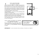
INSTALL THE RANGEHOOD
1.
Remove the rangehood from the carton and place on a
flat surface. Cover the surface to prevent accidental damage.
Remove all parts including the backdraft damper, plastic grille
and literature package before discarding the carton. Remove
the grease filters and set aside (see
FIGURE 7
on next page
for instructions.
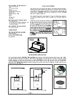
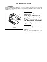
2.
Place the round damper into the exhaust opening of the
rangehood and press down.
FIGURE 4
3.
The rangehood mounts to the cabinet by two spring loaded
brackets, one on each side of the rangehood
(FIGURE 5)
. Lift
the rangehood into the cutout opening in the cabinet. Be careful
not to damage the cabinet, rangehood or other appliances.
CUT-OUT
PREPARE THE CABINET
1.
Disconnect and move freestanding range from cabinet
opening to provide easier access to upper cabinet and rear wall.
Put a thick, protective covering over cooktops, set-in ranges or
countertops to protect from damage or dirt.
2.
Determine and clearly mark with a pencil the center line
of the cabinet on the wall and on the underside of the cabinet
where the rangehood will be installed.
3.
If the cabinet bottom is recessed, wood blocks need to
be installed to insure proper alignment with the cabinet bottom.
Wood blocks should be flush or recessed 1/16" to 1/8" within
the cabinet bottom as indicated in
FIGURE 3
.
FIGURE 3
MAKE THE CUT-OUT OPENING (FIGURE 4)
WHERE THE RANGEHOOD WILL BE INSTALLED.
4.
Determine the proper cutouts for the ductwork. Make all
necessary cuts in the walls or cabinets for the ductwork. Install
the ductwork before mounting the rangehood.
5.
Determine and make the proper cutout for the Power Supply
Cable. Use a 1 1/4" Drill Bit to make this hole. Run the Power
Supply Cable through the wall or cabinet. DO NOT turn on the
power until installation is complete. Use caulking to seal around
the wire opening.
FIGURE 5
4. The spring loaded brackets are factory set to accomo-
date a thickness between 1 3/16" and 2 1/4". If your cabinet
bottom is less than 1 3/16" thick, the spring loaded brackets
can be removed and repositioned down from the top setting
to the bottom setting by removing the four phillips screws.
5.
Tighten the rangehood to the cabinet by rotating the
screws with a phillips screw driver.
6.
A metal trim strip
(FIGURE 6)
is included to cover the
underside of any remaining exposed cabinet. Attach the strip
to the bottom of the back of the rangehood with the three
screws provided.
7.
R
emove the cover from the field wiring compartment with
a phillips screwdriver. Feed the Power Supply Cable through
the electrical knockout. Connect the Power Supply Cable to the
rangehood cable. Attach the White lead of the power supply
to the White lead of the rangehood with a twist-on type wire
connector. Attach the Black lead of the power supply to the
Black lead of the rangehood with a twist-on type wire connector.
Attach the Power Supply Cable grounding lead to the green
screw provided. Using the 4 holes provided, screw the field
wiring compartment to the wall or cabinet as dictated by your
Power Supply Cable location (screws not provided). Replace
the cover.
8.
R
eplace the grease filters. Connect the ductwork to the
damper and seal all connections.
9.
Turn the power supply on. Turn on the blower and light.
If the rangehood does not operate, check that the circuit breaker
is not tripped or the house fuse blown. If the unit still does
not operate, disconnect the power supply and check that the
wiring connections have been made properly.
FIGURE 6
EN
88
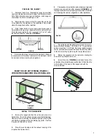
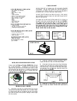
INSTALLATION
Drilling the Support surface and Fitting the Hood
SCREW FITTING
• The hood support surface must be 8” 11/16 above the bottom
surface of the wall units.
• Drill the support with a ø 3/16”drill bit, using the drilling tem-
plate provided.
• Cut a hole ø 6”in size on the support surface, using the drilling
template provided.
• Fix using the 4 screws
12a
provided.
����
����
���
SNAP-ON FITTING
• The hood can be installed either directly on the bottom surface
of the wall units using snap-on side supports.
• Cut a fitted opening in the bottom surface of the wall unit, as
shown.
• Insert the hood until the side supports snap into place.
• Lock in position by tightening the screws
Vf
from underneath
the hood.
�����
��������
��������������������
��
CLOSING ELEMENT
• The space between the edge of the hood and the rear wall can
be closed by applying the element
20
provided, using the
screws supplied for this purpose.
��
EN
88
INSTALLATION
Drilling the Support surface and Fitting the Hood
SCREW FITTING
• The hood support surface must be 8” 11/16 above the bottom
surface of the wall units.
• Drill the support with a ø 3/16”drill bit, using the drilling tem-
plate provided.
• Cut a hole ø 6”in size on the support surface, using the drilling
template provided.
• Fix using the 4 screws
12a
provided.
����
����
���
SNAP-ON FITTING
• The hood can be installed either directly on the bottom surface
of the wall units using snap-on side supports.
• Cut a fitted opening in the bottom surface of the wall unit, as
shown.
• Insert the hood until the side supports snap into place.
• Lock in position by tightening the screws
Vf
from underneath
the hood.
�����
��������
��������������������
��
CLOSING ELEMENT
• The space between the edge of the hood and the rear wall can
be closed by applying the element
20
provided, using the
screws supplied for this purpose.
��
19
3/4
"
10
3/8
"
Содержание Cristal 24 SS
Страница 35: ...35...
Страница 36: ...991 0531 907_01 180312 D00004241_00...


