


20
INFORMATIONS POUR L'UTILISATION ET L'ENTRETIEN
Pour de meilleurs résultats
Activez la hotte quelques minutes avant de commencer à cuisiner pour créer un flux d'air
adéquat. Laissez la hotte fonctionner quelques minutes après avoir fini de cuisiner pour
absorber toute la fumée et les odeurs de la cuisine.
Version 07/11 - Page 13
UTILISATION ET ENTRETIEN
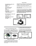
Panneau de commandes
Toutes les commandes sont situées sous le côté droit
arrière de la hotte.
Bouton marche-arrêt de la lumière
L'interrupteur marche-arrêt pour la lumière halogen est
située derrière la bande frontale. Régler à « 1 » pour
mettre en circuit (ON) et à « O » pour mettre hors circuit
(OFF).
Bouton de vitesse du ventilateur (B- FIGURE 10)
Régler à « 1 » pour vitesse basse (LOW), à « 2 » pour
vitesse moyenne (MÉDIUM) et à « 3 » pour vitesse élevée
(HIGH). Régler à « 0 »
pour mettre hors circuit (OFF).
Exécution Automatique
Tant que le ventilateur et les commutateurs légers
sont allumés, le ventilateur et la lumière fonctionneront
automatiquement quand le pare-soleil est ouvert et coupé
quand le pare-soleil est fermé.
Pour de meilleurs résultats
Mettre la hotte en circuit avant de commencer la cuisson.
Laisser l’appareil fonctionner quelques minutes après la
cuisson pour éliminer la fumée et les odeurs.
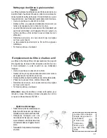
Nettoyage
Nettoyer régulièrement les filtres de métal avec une
solution d’eau chaude et de détergent ou mettre au lave-
vaisselle. Nettoyer les surfaces extérieures à l’eau chaude
savonneuse. Ne pas employer de produits abrasifs ou
de récurants qui endommagent les surfaces en acier
inoxydable.
FIGURE 8
FIGURE 10
Les filtres de graisse sont retirés en appuyant le traitement
du côté droit du filtre (le SCHÉMA 7). En substituant,
assurez-vous que les filtres sont correctement placés avec
les traitements du côté droit et visible. Il y a 2 filtres de
graisse, un dans la pièce de glissière dehors du capot,
l'autre dans le dos.
DÉPLACEMENT DE FILTRE DE GRAISSE
FIGURE 7
EN
1
2
12
CARE
Grease filters
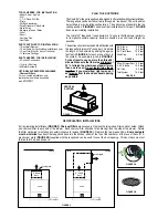
CLEANING METAL SELF- SUPPORTING GREASE FILTERS
• The filters must be cleaned every 2 months of operation, or
more frequently for particularly heavy usage, and can be
washed in a dishwasher.
• Remove the filters one at a time by pushing them towards the
back of the group and pulling up at the same time.
• Wash the filters, taking care not to bend them. Allow them to
dry before refitting.
• When refitting the filters, make sure that the handle is visible
on the outside.
Activated charcoal filter (Recirculating version)
These filters (not supplied with the rangehood)are not washable
and cannot be regenerated, and must be replaced approximately
every 4 months of operation, or more frequently with heavy us-
age.
REPLACING THE ACTIVATED CHARCOAL FILTER
• Remove the metal grease filters
• Remove the saturated activated charcoal filter as shown (
A
).
• Fit the new filters (
B
).z
• Replace the metal grease filters.
�
�
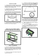
Lighting
LIGHT REPLACEMENT
20 W halogen light.
• Remove the 2 screws fixing the Lighting support, and pull it
out of from the Hood.
• Extract the lamp from the Support.
• Replace with another of the same type, making sure that the
two pins are properly inserted in the lamp holder socket holes.
• Replace the Support, fixing it in place with the two screws re-
moved as above.
EN
1
1
11
USE
Control board
L
Light
Switches the lighting system on and off.
M
Motor
Switches the extractor motor on and off.
V
Speed
Sets the operating speed of the extractor:
1. Low speed, used for a continuous and silent air change in the presence of
light cooking vapour.
2. Medium speed, suitable for most operating conditions given the optimum
treated air flow/noise level ratio.
3. Maximum speed, used for eliminating the highest cooking vapour emission,
including long periods.
�
�����
�
�
�
�
�
�
EN
1
2
12
CARE
Grease filter
s
CLEA
NING
META
LS
ELF-
SUP
PORTI
NG
GREA
SEFI
LTE
RS
•T
he
filte
rsm
ust
bec
lea
ned
eve
ry
2m
onthsof
opera
tion,
or
mor
ef
reque
ntlyf
or
partic
ularly
heav
yus
age
, a
ndc
an
be
wash
edin
ad
ish
wash
er.
•Re
mov
ethe
filte
rsone
at a
time
bypushing
the
mtow
ards
the
back
of the
group a
ndpul
ling u
pat
the sa
me ti
me.
•W
ash
thefilte
rs,ta
king
care
notto
ben
dth
em
.A
llo
wth
em
to
drybe
fore
refitting
.
•W
hen
refitting
thefilte
rs,m
ake
sure
that the
hand
leis
visible
onth
eo
utside
.
Activated charcoal filter
(Recirculating ver
sion)
The
se
filte
rs(not
supplie
dw
ithth
era
ngehood)a
re
not
was
hab
le
and
cannot
be
regenerat
ed,a
nd
must
be
replaced
appro
xim
atel
y
eve
ry
4m
onthsof
opera
tion,
orm
ore
fre
quently
with
heav
yus
-
age.
REPLACING
THE
ACTIVAT
EDCHA
RCOAL
FIL
TER
•Re
mov
ethe
meta
l gre
ase
filte
rs
•Re
mov
ethe
satura
ted
activ
ated
cha
rco
al f
iltera
sshow
n(
A
).
•Fit t
hene
wfilte
rs (
B
).z
•Rep
lace
them
etal
greas
efilters
.
�
�
Lighting
LIG
HT
REPLACEMENT
20
Whal
oge
nli
ght
.
•R
em
ove
the2
scr
ews
fix
ing
theL
igh
tings
uppor
t, a
nd
pullit
outof
fro
m the
Hoo
d.
•Ex
tract the
lam
pfr
om
theSupp
ort.
•Rep
lace
with
anot
her
of
the
samety
pe,
maki
ng
sure
that
the
two pins
are
prope
rly
ins
erte
d in
the
lam
p holde
r so
cke
t hole
s.
•Rep
lace
the
Supp
ort,
fixi
ng
iti
np
lace
with
the
two
screws re-
mov
edas
abov
e.
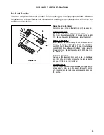
FIGURE 9
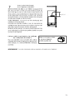
Remplacement de la lumière halogène
Avant d’essayer de remplacer les ampoules, s’assurer
que l’interrupteur soit hors circuit. Retirer les deux vis
(de la FIGURE 8)
.
Retirer l’ampoule et la remplacer
par une nouvelle ampoule.
Une méthode alternative pour substituer les lampes est
d'utiliser des 1 1/4"tasses d'aspiration
(de la FIGURE
9)
. Attachez la tasse d'aspiration à l'ampoule et tirez
fermement vers le bas sur l'ampoule et la substituez
avec une nouvelle lampe.la marche à suivre.
B
Version 07/11 - Page 13
UTILISATION ET ENTRETIEN
Panneau de commandes
Toutes les commandes sont situées sous le côté droit
arrière de la hotte.
Bouton marche-arrêt de la lumière
L'interrupteur marche-arrêt pour la lumière halogen est
située derrière la bande frontale. Régler à « 1 » pour
mettre en circuit (ON) et à « O » pour mettre hors circuit
(OFF).
Bouton de vitesse du ventilateur (B- FIGURE 10)
Régler à « 1 » pour vitesse basse (LOW), à « 2 » pour
vitesse moyenne (MÉDIUM) et à « 3 » pour vitesse élevée
(HIGH). Régler à « 0 »
pour mettre hors circuit (OFF).
Exécution Automatique
Tant que le ventilateur et les commutateurs légers
sont allumés, le ventilateur et la lumière fonctionneront
automatiquement quand le pare-soleil est ouvert et coupé
quand le pare-soleil est fermé.
Pour de meilleurs résultats
Mettre la hotte en circuit avant de commencer la cuisson.
Laisser l’appareil fonctionner quelques minutes après la
cuisson pour éliminer la fumée et les odeurs.
Nettoyage
Nettoyer régulièrement les filtres de métal avec une
solution d’eau chaude et de détergent ou mettre au lave-
vaisselle. Nettoyer les surfaces extérieures à l’eau chaude
savonneuse. Ne pas employer de produits abrasifs ou
de récurants qui endommagent les surfaces en acier
inoxydable.
FIGURE 8
FIGURE 10
Les filtres de graisse sont retirés en appuyant le traitement
du côté droit du filtre (le SCHÉMA 7). En substituant,
assurez-vous que les filtres sont correctement placés avec
les traitements du côté droit et visible. Il y a 2 filtres de
graisse, un dans la pièce de glissière dehors du capot,
l'autre dans le dos.
DÉPLACEMENT DE FILTRE DE GRAISSE
FIGURE 7
EN
1
2
12
CARE
Grease filters
CLEANING METAL SELF- SUPPORTING GREASE FILTERS
• The filters must be cleaned every 2 months of operation, or
more frequently for particularly heavy usage, and can be
washed in a dishwasher.
• Remove the filters one at a time by pushing them towards the
back of the group and pulling up at the same time.
• Wash the filters, taking care not to bend them. Allow them to
dry before refitting.
• When refitting the filters, make sure that the handle is visible
on the outside.
Activated charcoal filter (Recirculating version)
These filters (not supplied with the rangehood)are not washable
and cannot be regenerated, and must be replaced approximately
every 4 months of operation, or more frequently with heavy us-
age.
REPLACING THE ACTIVATED CHARCOAL FILTER
• Remove the metal grease filters
• Remove the saturated activated charcoal filter as shown (
A
).
• Fit the new filters (
B
).z
• Replace the metal grease filters.
�
�
Lighting
LIGHT REPLACEMENT
20 W halogen light.
• Remove the 2 screws fixing the Lighting support, and pull it
out of from the Hood.
• Extract the lamp from the Support.
• Replace with another of the same type, making sure that the
two pins are properly inserted in the lamp holder socket holes.
• Replace the Support, fixing it in place with the two screws re-
moved as above.
EN
1
1
11
USE
Control board
L
Light
Switches the lighting system on and off.
M
Motor
Switches the extractor motor on and off.
V
Speed
Sets the operating speed of the extractor:
1. Low speed, used for a continuous and silent air change in the presence of
light cooking vapour.
2. Medium speed, suitable for most operating conditions given the optimum
treated air flow/noise level ratio.
3. Maximum speed, used for eliminating the highest cooking vapour emission,
including long periods.
�
�����
�
�
�
�
�
�
EN
1
2
12
CARE
Grease filter
s
CLEA
NING
META
LS
ELF-
SUP
PORTI
NG
GREA
SEFI
LTE
RS
•T
he
filte
rsm
ust
bec
lea
ned
eve
ry
2m
onthsof
opera
tion,
or
mor
ef
reque
ntlyf
or
partic
ularly
heav
yus
age
, a
ndc
an
be
wash
edin
ad
ish
wash
er.
•Re
mov
ethe
filte
rsone
at a
time
bypushing
the
mtow
ards
the
back
of the
group a
ndpul
ling u
pat
the sa
me ti
me.
•W
ash
thefilte
rs,ta
king
care
notto
ben
dth
em
.A
llo
wth
em
to
drybe
fore
refitting
.
•W
hen
refitting
thefilte
rs,m
ake
sure
that the
hand
leis
visible
onth
eo
utside
.
Activated charcoal filter
(Recirculating ver
sion)
The
se
filte
rs(not
supplie
dw
ithth
era
ngehood)a
re
not
was
hab
le
and
cannot
be
regenerat
ed,a
nd
must
be
replaced
appro
xim
atel
y
eve
ry
4m
onthsof
opera
tion,
orm
ore
fre
quently
with
heav
yus
-
age.
REPLACING
THE
ACTIVAT
EDCHA
RCOAL
FIL
TER
•Re
mov
ethe
meta
l gre
ase
filte
rs
•Re
mov
ethe
satura
ted
activ
ated
cha
rco
al f
iltera
sshow
n(
A
).
•Fit t
hene
wfilte
rs (
B
).z
•Rep
lace
them
etal
greas
efilters
.
�
�
Lighting
LIG
HT
REPLACEMENT
20
Whal
oge
nli
ght
.
•R
em
ove
the2
scr
ews
fix
ing
theL
igh
tings
uppor
t, a
nd
pullit
outof
fro
m the
Hoo
d.
•Ex
tract the
lam
pfr
om
theSupp
ort.
•Rep
lace
with
anot
her
of
the
samety
pe,
maki
ng
sure
that
the
two pins
are
prope
rly
ins
erte
d in
the
lam
p holde
r so
cke
t hole
s.
•Rep
lace
the
Supp
ort,
fixi
ng
iti
np
lace
with
the
two
screws re-
mov
edas
abov
e.
FIGURE 9
Remplacement de la lumière halogène
Avant d’essayer de remplacer les ampoules, s’assurer
que l’interrupteur soit hors circuit. Retirer les deux vis
(de la FIGURE 8)
.
Retirer l’ampoule et la remplacer
par une nouvelle ampoule.
Une méthode alternative pour substituer les lampes est
d'utiliser des 1 1/4"tasses d'aspiration
(de la FIGURE
9)
. Attachez la tasse d'aspiration à l'ampoule et tirez
fermement vers le bas sur l'ampoule et la substituez
avec une nouvelle lampe.la marche à suivre.
B
Содержание Cristal 24 SS
Страница 35: ...35...
Страница 36: ...991 0531 907_01 180312 D00004241_00...


