


29
Version 07/11 - Page 6
INSTALL THE RANGEHOOD
1.
Remove the rangehood from the carton and place on a
flat surface. Cover the surface to prevent accidental damage.
Remove all parts including the backdraft damper, plastic grille
and literature package before discarding the carton. Remove
the grease filters and set aside (see
FIGURE 7
on next page
for instructions.
2.
Place the round damper into the exhaust opening of the
rangehood and press down.
FIGURE 4
3.
The rangehood mounts to the cabinet by two spring loaded
brackets, one on each side of the rangehood
(FIGURE 5)
. Lift
the rangehood into the cutout opening in the cabinet. Be careful
not to damage the cabinet, rangehood or other appliances.
CUT-OUT
PREPARE THE CABINET
1.
Disconnect and move freestanding range from cabinet
opening to provide easier access to upper cabinet and rear wall.
Put a thick, protective covering over cooktops, set-in ranges or
countertops to protect from damage or dirt.
2.
Determine and clearly mark with a pencil the center line
of the cabinet on the wall and on the underside of the cabinet
where the rangehood will be installed.
3.
If the cabinet bottom is recessed, wood blocks need to
be installed to insure proper alignment with the cabinet bottom.
Wood blocks should be flush or recessed 1/16" to 1/8" within
the cabinet bottom as indicated in
FIGURE 3
.
FIGURE 3
MAKE THE CUT-OUT OPENING (FIGURE 4)
WHERE THE RANGEHOOD WILL BE INSTALLED.
4.
Determine the proper cutouts for the ductwork. Make all
necessary cuts in the walls or cabinets for the ductwork. Install
the ductwork before mounting the rangehood.
5.
Determine and make the proper cutout for the Power Supply
Cable. Use a 1 1/4" Drill Bit to make this hole. Run the Power
Supply Cable through the wall or cabinet. DO NOT turn on the
power until installation is complete. Use caulking to seal around
the wire opening.
FIGURE 5
4. The spring loaded brackets are factory set to accomo-
date a thickness between 1 3/16" and 2 1/4". If your cabinet
bottom is less than 1 3/16" thick, the spring loaded brackets
can be removed and repositioned down from the top setting
to the bottom setting by removing the four phillips screws.
5.
Tighten the rangehood to the cabinet by rotating the
screws with a phillips screw driver.
6.
A metal trim strip
(FIGURE 6)
is included to cover the
underside of any remaining exposed cabinet. Attach the strip
to the bottom of the back of the rangehood with the three
screws provided.
7.
R
emove the cover from the field wiring compartment with
a phillips screwdriver. Feed the Power Supply Cable through
the electrical knockout. Connect the Power Supply Cable to the
rangehood cable. Attach the White lead of the power supply
to the White lead of the rangehood with a twist-on type wire
connector. Attach the Black lead of the power supply to the
Black lead of the rangehood with a twist-on type wire connector.
Attach the Power Supply Cable grounding lead to the green
screw provided. Using the 4 holes provided, screw the field
wiring compartment to the wall or cabinet as dictated by your
Power Supply Cable location (screws not provided). Replace
the cover.
8.
R
eplace the grease filters. Connect the ductwork to the
damper and seal all connections.
9.
Turn the power supply on. Turn on the blower and light.
If the rangehood does not operate, check that the circuit breaker
is not tripped or the house fuse blown. If the unit still does
not operate, disconnect the power supply and check that the
wiring connections have been made properly.
FIGURE 6
EN
88
INSTALLATION
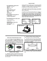
Drilling the Support surface and Fitting the Hood
SCREW FITTING
• The hood support surface must be 8” 11/16 above the bottom
surface of the wall units.
• Drill the support with a ø 3/16”drill bit, using the drilling tem-
plate provided.
• Cut a hole ø 6”in size on the support surface, using the drilling
template provided.
• Fix using the 4 screws
12a
provided.
����
����
���
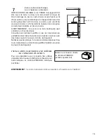
SNAP-ON FITTING
• The hood can be installed either directly on the bottom surface
of the wall units using snap-on side supports.
• Cut a fitted opening in the bottom surface of the wall unit, as
shown.
• Insert the hood until the side supports snap into place.
• Lock in position by tightening the screws
Vf
from underneath
the hood.
�����
��������
��������������������
��
CLOSING ELEMENT
• The space between the edge of the hood and the rear wall can
be closed by applying the element
20
provided, using the
screws supplied for this purpose.
��
EN
88
INSTALLATION
Drilling the Support surface and Fitting the Hood
SCREW FITTING
• The hood support surface must be 8” 11/16 above the bottom
surface of the wall units.
• Drill the support with a ø 3/16”drill bit, using the drilling tem-
plate provided.
• Cut a hole ø 6”in size on the support surface, using the drilling
template provided.
• Fix using the 4 screws
12a
provided.
����
����
���
SNAP-ON FITTING
• The hood can be installed either directly on the bottom surface
of the wall units using snap-on side supports.
• Cut a fitted opening in the bottom surface of the wall unit, as
shown.
• Insert the hood until the side supports snap into place.
• Lock in position by tightening the screws
Vf
from underneath
the hood.
�����
��������
��������������������
��
CLOSING ELEMENT
• The space between the edge of the hood and the rear wall can
be closed by applying the element
20
provided, using the
screws supplied for this purpose.
��
19
3/4
"
10
3/8
"
PREPARAR EL ARMARIO
1. Desconecte y mueva la campana independiente de la apertura
del armario para facilitar el acceso al armario superior y a la pared
posterior. Coloque una cubierta gruesa y protectora sobre las placas
de cocción, las cocinas empotradas o las encimeras para protegerlas
de daños o suciedad.
2. Determine y marque claramente con un lápiz la línea central
del armario en la pared y en la parte inferior del armario, donde se
instalará la campana.
3. Si el fondo del armario está empotrado, se deben instalar bloques
de madera para asegurar una alineación apropiada con el fondo del
armario. Los bloques de madera deben estar a ras o empotrados de
1/16" a 1/8" dentro de la parte inferior del armario, como se indica en
la FIGURA 3.
4. Determine los recortes apropiados para los conductos. Haga
todos los recortes necesarios en las paredes o armarios para el
conducto. Instale la red de conductos antes de montar la campana
5. Determine y realice el recorte adecuado para el cable de alimen-
tación. Utilice una broca de 1 1/4" para hacer este agujero. Pase el
cable de suministro de energía a través de la pared o el armario. NO
encienda la unidad hasta que se haya completado la instalación. Use
masilla para sellar alrededor de la abertura del cable.
HAGA LA ABERTURA DE RECORTE (FIGURA 4)
DONDE: SE INSTALARÁ LA CAMPANA.
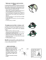
INSTALE LA CAMPANA
1. Retire la campana de la caja y colóquela sobre una superficie
plana. Cubra la superficie para evitar daños accidentales. Retire
todas las piezas, incluyendo el registro de contraflujo, la rejilla de
plástico y el paquete de documentación antes de desechar el cartón.
Retire los filtros de grasa y déjelos a un lado (vea la FIGURA 7 en la
página siguiente para obtener instrucciones).
2. Coloque el amortiguador redondo en la abertura de escape de la
campana y presione hacia abajo.
3. La campana se monta en el armario por medio de
dos soportes cargados con resortes, uno a cada lado de
la campana (FIGURA 5). Levante la campana hasta la
abertura de recorte en el armario. Tenga cuidado de no
dañar el armario, la campana u otros dispositivos.
4. Los soportes cargados por resorte se ajustan en fá-
brica para acomodar un grosor entre 1 3/16" y 2 1/4". Si
el fondo de su armario tiene un grosor inferior a 1 3/16",
los soportes cargados por resorte se pueden retirar y
reposicionar desde el ajuste superior hasta el ajuste
inferior quitando los cuatro tornillos phillips.
5. Apriete la campana al armario girando los tornillos con
un destornillador phillips.
6. Se incluye una tira de ajuste metálica (FIGURA 6)
para cubrir la parte inferior de cualquier armario expues-
to restante. Coloque la tira en la parte inferior trasera de
la campana con los tres tornillos provistos.
Содержание Cristal 24 SS
Страница 35: ...35...
Страница 36: ...991 0531 907_01 180312 D00004241_00...


