


17
Version 07/11 - Page 11
OUTILS NÉCESSAIRES À L’INSTALLATION
• Scie sauteuse ou à découper
• Perceuse
• Mèche à bois 1 1/4 po
• Pinces
• Tournevis Phillips
• Dénude fil ou couteau tout usage
• Pince coupante à fil métallique
• Ruban à mesurer ou règle
• Niveau
• Crayon
• Outil à calfeutrage
• Ruban à conduit
PIÈCES FOURNIES POUR L’INSTALLATION
• 1 registre à clapet
• Une grille (Pour Recirculation D'air)
• 1 nécessaire de documentation
PIÈCES NÉCESSAIRES POUR L’INSTALLATION
• 2 connecteurs de conduit
• Câble d’alimentation
• 1 capuchon de mur ou de toit
• Conduit en métal
ACCESSOIRES POUR L’INSTALLATION
• Filtres au Charbon
Pour installation sans conduit
part #
FILTER1
PLAN DU CONDUIT
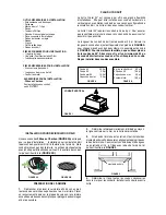
La hotte Cristal 24" est conçue pour offrir une grande flexibilité
d’installations
.
Elle peut être installée avec conduit horizontal ou
vertical par une ventilation rond de 6 po ou avec une configuration de
recirculation d’air
.
La hotte arrives avec conduit vertical.
La hotte Cristal 24" requiert
le conduit rond de 6 po. Pour assurer
que le ventilateur marche le mieux, le conduit doit être aussi court et
aussi droit que possible.
La longueur du conduit ne doit jamais excéder 35 pi. Calculer la
longueur du conduit en ajoutant l’équivalent en pied de la
FIGURE A
pour chaque pièce du conduit du système. Un exemple est donné à
la
FIGURE B
.
Pour de meilleurs résultats, ne pas utiliser plus de
trois coudes de 90
o
. S’assurer qu’il y ait un minimum de 24 po
de conduit droit entre les coudes si l’on utilise plus d’un coude.
Ne pas installer deux coudes ensemble.
INSTALLATION POUR RECIRCULATION D'AIR
Un nécessaire des
Filtres au Charbon
(FIGURE 2A)
est requis
pour ce type d'installation. Installation pour recirculaton d'air
requis conduit pour divertir l'air à l'extérieur de l'armoire. Ne la
conduit terminez pas dan l'armoire. La grille en plastique fournie
avec la hotte peut être utilisée pour couvrir l’ouverture du conduit,
tel qu’il est illustré à la
(FIGURE 2B)
.
FIGURE 2A
FIGURE 2B
Coude 45˚
Coude 90˚
Coude plat 90˚
Capuchon de mur
FIGURE A
9 pi de conduit droit
2 Coudes 90˚
Capuchon de mur
Système total
9,0 pi
10,0 pi
0,0 pi
19,0 pi
FIGURE B
3ß,0 pi
5,0 pi
12,0 pi
0,0 pi
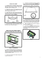
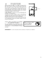
CONDUIT VERTICAL
FIGURE 1
2.
Déterminer et marquer clairement, à l’aide d’un crayon,
la ligne centrale sur le mur où la hotte sera installée.
3.
Si le bas de l’armoire est en retrait, il faut installer des
montants en bois afin d’assurer un alignement approprié avec
le bas de l’armoire. Ces montants en bois doivent être égaux
ou en retrait de 1/16 à 1/8 po avec le bas de l’armoire, tel
qu’il est illustré à la
FIGURE 3
.
FIGURE 3
PRÉPARATION DE L'ARMOIRE
1.
Débrancher et enlever la cuisinière afin d’avoir un meil
-
leur accès aux armoires supérieures et au mur arrière. Placer
un recouvrement épais sur la plaque de cuisson, la cuisinière
encastrée ou le dessus du comptoir pour protéger des dommages
et de la poussière.
4.
Déterminer et faire toutes les coupes nécessaires
dans le mur pour les conduits. Installer les conduits avant la
hotte.
5.
Déterminer l’emplacement approprié pour le câble
d’alimentation. Utiliser une mèche de 1
1/4
po pour faire un
trou et y passer le câble d’alimentation. Utiliser du calfeutrage
pour sceller tout autour du trou. NE PAS mettre en circuit tant
que l’installation n’est pas complétée.
montants en bois
EN
1
2
12
CARE
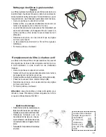
Grease filters
CLEANING METAL SELF- SUPPORTING GREASE FILTERS
• The filters must be cleaned every 2 months of operation, or
more frequently for particularly heavy usage, and can be
washed in a dishwasher.
• Remove the filters one at a time by pushing them towards the
back of the group and pulling up at the same time.
• Wash the filters, taking care not to bend them. Allow them to
dry before refitting.
• When refitting the filters, make sure that the handle is visible
on the outside.
Activated charcoal filter (Recirculating version)
These filters (not supplied with the rangehood)are not washable
and cannot be regenerated, and must be replaced approximately
every 4 months of operation, or more frequently with heavy us-
age.
REPLACING THE ACTIVATED CHARCOAL FILTER
• Remove the metal grease filters
• Remove the saturated activated charcoal filter as shown (
A
).
• Fit the new filters (
B
).z
• Replace the metal grease filters.
�
�
Lighting
LIGHT REPLACEMENT
20 W halogen light.
• Remove the 2 screws fixing the Lighting support, and pull it
out of from the Hood.
• Extract the lamp from the Support.
• Replace with another of the same type, making sure that the
two pins are properly inserted in the lamp holder socket holes.
• Replace the Support, fixing it in place with the two screws re-
moved as above.
Version 07/11 - Page 5
9.0 feet
10.0 feet
0.0 feet
19.0 feet
TOOLS NEEDED FOR INSTALLATION
• Saber Saw or Jig Saw
• Drill
• 1 1/4" Wood Drill Bit
• Pliers
• Phillips Screwdriver
• Wire Stripper or Utility Knife
• Metal Snips
• Measuring Tape or Ruler
• Level
• Pencil
• Caulking Gun
• Duct Tape
PARTS SUPPLIED FOR INSTALLATION
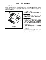
• 1 Backdraft Damper
• 1 Vent Grate (for recirculating installations only)
• 1 Rear Trim Strip (for back of the hood)
• 1 Literature Package
PARTS NEEDED FOR INSTALLATION
• 2 Conduit Connectors
• Power Supply Cable
• 1 Wall or Roof Cap
• All Metal Ductwork
OPTIONAL ACCESSORIES AVAILABLE
• Charcoal Filters
For non-vented installations only,
replace charcoal filters as needed
part #
FILTER1
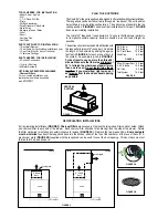
PLAN THE DUCTWORK
The Cristal 24" slideout rangehood is designed to offer wide flexibility of installations.
The rangehood can be ducted vertically through a 6" round vent. The unit can also
be installed in a recirculating configuration. The unit comes standard in the top
venting position.
FIGURES 1
shows vertical installations for this unit.
FIGURE
2
shows recirculating installation.
The Cristal 24" requires 6" round ductwork. To ensure that the blower performs
to its highest possible capacity, ductwork should be as short and straight as
possilbe.
RECIRCULATING INSTALLATIONS
For recirculating installations
(FIGURE 2)
,
Charcoal Filters
are necessary. Remove the two grease filters and set aside. Attach
one charcoal filter to each end of the blower. Each charcoal filter attaches to the black grid on the side of the blower. Rotate
the filter clockwise to install and counterclockwise to remove
(FIGURE 2A)
. Replace the two grease filters.
Some ductwork
must be installed
to exhaust the rangehood back into the kitchen, either at the top of the cabinet or at the face of the soffit. A
plastic vent grate
(FIGURE 2B)
supplied with the rangehood can be used to cover the duct opening. This duct work must not
terminate into a dead air space.
FIGURE 2A
45˚ Elbow
90˚ Elbow
90˚ Flat Elbow
Wall Cap
FIGURE A
9 Feet Straight Duct
2 - 90˚ Elbows
Wall Cap
Total System
FIGURE B
3.0 feet
5.0 feet
12.0 feet
0.0 feet
VERTICAL
DUCTING
FIGURE 1
cabinet
ceiling
6” round
duct
hood
cabinet
ceiling
6” round
duct
hood
soffit
vent grate
vent grate
FIGURE 2B
FIGURE 2
The ductrun should not exceed 35 feet if ducted with
the required minimum of 6" round duct. Calculate
the length of the ductwork by adding the equiva-
lent feet in
FIGURE A
for each piece of duct in
the system An example is given in
FIGURE B
.
For best results, use no more than three 90°
elbows. Make sure that there is a minimum of
24" of straight duct between elbows if more
than one is used. Do not install two elbows
together. If you must elbow right away, do it
as far away from the hood's exhaust opening
as possible.
EN
1
2
12
CARE
Grease filters
CLEANING METAL SELF- SUPPORTING GREASE FILTERS
• The filters must be cleaned every 2 months of operation, or
more frequently for particularly heavy usage, and can be
washed in a dishwasher.
• Remove the filters one at a time by pushing them towards the
back of the group and pulling up at the same time.
• Wash the filters, taking care not to bend them. Allow them to
dry before refitting.
• When refitting the filters, make sure that the handle is visible
on the outside.
Activated charcoal filter (Recirculating version)
These filters (not supplied with the rangehood)are not washable
and cannot be regenerated, and must be replaced approximately
every 4 months of operation, or more frequently with heavy us-
age.
REPLACING THE ACTIVATED CHARCOAL FILTER
• Remove the metal grease filters
• Remove the saturated activated charcoal filter as shown (
A
).
• Fit the new filters (
B
).z
• Replace the metal grease filters.
�
�
Lighting
LIGHT REPLACEMENT
20 W halogen light.
• Remove the 2 screws fixing the Lighting support, and pull it
out of from the Hood.
• Extract the lamp from the Support.
• Replace with another of the same type, making sure that the
two pins are properly inserted in the lamp holder socket holes.
• Replace the Support, fixing it in place with the two screws re-
moved as above.
Содержание Cristal 24 SS
Страница 35: ...35...
Страница 36: ...991 0531 907_01 180312 D00004241_00...


