Extron electronics RSB 126 Скачать руководство пользователя страница 18

SW USB Series • Operation

Operation, cont’d

3-4

SW USB Series • Operation


3-5

Selecting an input using contact closure

Use one of the following methods to select an input via contact 

closure: 


Using a contact closure device:

 If a two- or four-button 

contact closure device is connected to the SW USB’s 

Contact port, press the button on the device that 

corresponds to the SW USB input that you want to select 

(the first button on the left selects input 1, the second 

button selects input 2, etc.).


Using a jumper wire: 

On the Contact port, insert one end 

of a small piece of wire into the ground (

_

) port and the 

other end into the port with the desired input number (1, 2, 

3, or 4). 


Using an IR 102:

 Refer to your 

IR 102 User’s Manual

 for 

this procedure.

Selecting an input using SIS commands

You can also select an input via an RS-232 connection, using SIS 

commands.  See chapter 4, “SIS Configuration and Control,” for 

a list of available SIS commands and their explanations.  
If an Extron A/V switcher is connected to the RS-232 Pass 

Thru port, the SIS commands that you enter can also be passed 

through to the connected switcher, even if the connected 

switcher has more inputs than the SW USB (see the next section). 

Issuing commands to an Extron A/V switcher via 

the RS-232 Pass Thru port

You can configure the SW USB to pass commands through 

the RS-232 Pass Thru port to a connected A/V switcher in the 

following modes:


Loop 1 mode: 

SIS commands that are issued to the 

SW USB via an RS-232 interface (such as HyperTerminal) 

on a computer or control system connected to the 

SW USB’s RS-232 port can be passed through to an A/V 

switcher connected to the RS-232 Pass Thru port.    


Loop 1 mode is the default mode.  If you need to switch 

the SW USB to this mode, enter the SIS command 

E

1

LOOP

}

.   


Loop 0 mode:

 The input selection SIS command 

X!


!


(where 

X!

 is the input number) can be issued to the 

SW USB and the connected A/V switcher via the buttons 

on the SW USB front panel, contact closure, or the RS-232 

interface.  


To enable Loop 0 mode, enter the SIS command 

E

 0LOOP

}

.

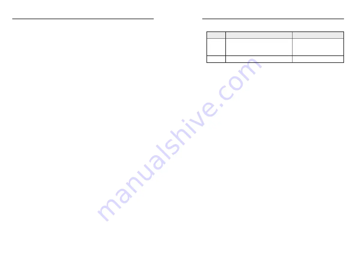
The following table summarizes the two loop modes:

Mode

SIS commands issued via:

SIS command to enable

Loop 0

Contact closure, front panel,  
or RS-232 interface (Input  
selection SIS command 

X!

 ! only)

E

 0LOOP 

}

Loop 1

RS-232 interface* 

E

 1LOOP 

}

* See the command/response table in chapter 4, “SIS  

Configuration and Control,” for an explanation of all supported 

SIS commands.

SIS command processing in Loop 1 mode

When an A/V switcher is connected to the RS-232 Pass Thru 

port and Loop 1 mode is enabled, the available SIS commands 

are processed in one of the following ways:


Passed through  to the A/V switcher without being acted 

on by the SW USB  


Performed by the SW USB and not passed through to the 

A/V switcher


Performed by the SW USB and passed to the A/V switcher, 

which also performs them.  This applies only to the input 

selection command 

X!


!

.   

The table on the next page shows how the SIS commands are 

handled by an SW USB with a connected A/V switcher.  (Unless 

otherwise indicated, commands are 

not

 case-sensitive.)        

Содержание RSB 126

Страница 1: ...919 863 1797 FAX Extron Europe 800 3987 6673 Inside Europe Only 31 33 453 4040 31 33 453 4050 FAX Extron Asia 800 7339 8766 Inside Asia Only 65 6383 4400 65 6383 4664 FAX Extron Japan 81 3 3511 7655 8...

Страница 2: ...sollten Sie alle Netzkabel aus der R ckseite des Ger tes aus der externen Stomversorgung falls dies m glich ist oder aus der Wandsteckdose ziehen Schutz des Netzkabels Netzkabel sollten stets so verl...

Страница 3: ...e undesired operation The Class A limits are designed to provide reasonable protection against harmful interference when the equipment is operated in a commercial environment This equipment generates...

Страница 4: ...port and to a host computer or control system See Wiring for RS 232 Communication in chapter 2 Installation N Your RS 232 computer or control system should not be one of the host devices connected to...

Страница 5: ...A Audio Switcher Desktop PC 1 Desktop PC 3 Desktop PC 4 RS 232 Loop Out Extron SW4 USB Plus USB Switcher USB RS 232 RS 232 Control System Mouse Keyboard VGA Outputs Desktop PC 2 Table of Contents Chap...

Страница 6: ...ble 4 3 Symbol definitions 4 3 Updating the Firmware 4 6 Downloading and installing the Firmware Loader 4 6 Downloading and installing the SW USB firmware 4 7 Loading the firmware to the SW USB using...

Страница 7: ...revent unauthorized access to the switchers executive mode can be enabled via the front panel or SIS commands When the switcher is in executive mode all front panel controls are disabled About this Ma...

Страница 8: ...S THR U US B OU TP UT HU B US B 3 US B 1 PC 1 PC 2 PC 3 PC 4 US B 2 US B 4 1 5A MAX 12V POW ER Extron SW4 USB USB USB RS 232 Loop Out RS 232 VGA Outputs VGA VGA Out Annotator Projector Control System...

Страница 9: ...SW USB Series 2 Chapter Two Installation Installation Overview Mounting the SW USB Series Switcher Rear Panel Features Wiring the Power Connector Wiring for RS 232 Communication Contact Closure Contro...

Страница 10: ...3 Operation 9 Power on the USB peripheral devices if applicable 10 Power on the SW USB switcher 11 Power on the host device s Mounting the SW USB Series Switcher The SW USB Series switcher can be set...

Страница 11: ...that circuit overloading might have on overcurrent protection and supply wiring Consider equipment nameplate ratings when addressing this concern 5 Reliable earthing grounding Maintain reliable ground...

Страница 12: ...type B USB connectors using cable lengths of up to 15 4 5 m Pinouts for these connectors follow the standard pinout as defined in USB specifications 3 7 9 Preparing the SW USB for under desk mounting...

Страница 13: ...controlled via Extron s Simple Instruction Set SIS commands This port can also be used to update firmware N Your RS 232 computer or control system should not be one of the host devices connected to t...

Страница 14: ...ge shows how to wire the SW USB s RS 232 Pass Thru port for use with an Extron A V switcher The SW USB s RS 232 Pass Thru port does not have a receive pin therefore it does not receive responses from...

Страница 15: ...o the RS 232 Pass Thru port an input selection command issued via contact closure selects the same input on both the SW USB and the connected switcher US B SW ITCH IN G IN PU T Tx Tx Rx RS 23 2 CO NT...

Страница 16: ...SWITCHER EXEC MODE 1 2 3 4 1 2 3 4 INPUT 1 2 3 4 OUTPUT ACTIVE USB SW4 USB Plus USB SWITCHER EXEC MODE 1 2 3 4 1 2 3 4 INPUT 1 2 3 4 OUTPUT ACTIVE USB SW4 USB Plus USB SWITCHER EXEC MODE 1 2 3 4 1 2...

Страница 17: ...ut is currently selected e Output LEDs Each of these LEDs lights when a peripheral device is connected to the switcher s corresponding output port and has been enabled by the selected input device or...

Страница 18: ...commands that are issued to the SW USB via an RS 232 interface such as HyperTerminal on a computer or control system connected to the SW USB s RS 232 port can be passed through to an A V switcher conn...

Страница 19: ...switcher using contact closure In Loop 0 mode you can select an input on the SW USB by shorting the equivalent pin on the Contact port to ground either by pressing a button on a connected contact clo...

Страница 20: ...upported by the emulation feature If you plan to use such devices set the Host Emulation DIP switches to off Examples of non standard keyboards or mice include media keyboards or five button mice 1 2...

Страница 21: ...ion with that keyboard or mouse Peripheral emulation SW4 USB Plus only In addition the SW4 USB Plus emulates a mouse and keyboard to the computer or other input device that is connected to the selecte...

Страница 22: ...SWn USB Switcher Series Vx xx The switcher sends the copyright message when it first powers on Vx xx is the firmware version number N This message is displayed only at power up Error responses If the...

Страница 23: ...nd host to unit Response unit to host Additional description Input selection Select input X Chn X Select input X for both the SW USB and the attached A V switcher if any Select SW USB input only X USB...

Страница 24: ...xe button where n is the Firmware Loader version number 5 Follow the instructions on the rest of the download screens to save the executable Firmware Loader installer file to the computer Note the fol...

Страница 25: ...e firmware on the previous page 3 Open the Firmware Loader via your desktop Start menu by making the following selections Start All Programs Extron Electronics Firmware Loader Firmware Loader 5 On the...

Страница 26: ...ocess is interrupted or the Firmware Loader exits before the upload is complete the unit is reset to its factory defaults 11 When the firmware upload process is completed the message Transfer Complete...

Страница 27: ...SW USB Series SIS Configuration and Control SIS Configuration and Control cont d 4 12 SW USB Series A Appendix A Specifications Part Numbers Accessories Specifications Included Parts Accessories...

Страница 28: ...are subject to change without notice Specifications USB USB specification USB 2 0 compatible USB data rates Low speed 1 5 Mbps Full speed 12 Mbps High speed 480 Mbps USB input Connectors SW2 USB 2 fe...

Страница 29: ...es Accessory Part Number CCR 2BLB Two Button Contact Closure Remote With Backlit Buttons 70 589 02 03 CCR 4BLB Two Button Contact Closure Remote With Backlit Buttons 70 588 02 03 CCR 204 Four Button C...

Страница 30: ...SW USB Series Specifications Part Numbers Accessories Specifications Part Numbers Accessories cont d A 6 This page was intentionally left blank...

Отзывы: