background image

HC 404 System • Hardware Features and Installation

8

Front Panel Features


CONFIG

HCR 102

1

INPUT

LPCM-2CH
MULTI-CH

HDCP

SIGNAL

R

MENU

ENTER

HOLD    FOR 720p/1080p

1

HCT 103

2

3

4

INPUTS

HDCP

SIGNAL

2

3

4

AUDIO

HCR 102

A

I J

B

C

D

H

FG

E

HCT 103

B

C

D


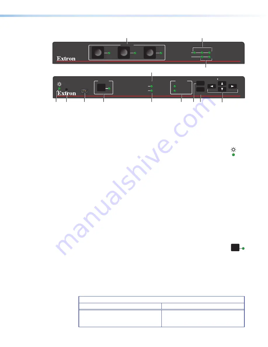
Figure 2. 

HCT 103 Front Panel (Top) HCR 102 Front Panel (Bottom)

Reset Features

J


Reset button

 — Pressing this recessed button (figure 2, 

J

, above) causes various 

product settings to be reset to the factory defaults. 

I


Reset and power LED

— This green LED (see 

I

) indicates either the power  

status of the receiver, or the reset mode. LED indications are as follows:

• 

Off

 — The HCR 102 is not powered on.

• 

On, lit steadily

 — The HCR 102 is powered on.

• 

Blinking

 — The unit is performing a reset or is powering up. The blink pattern 

depends on the selected reset mode.

For full descriptions of reset modes, how to use the reset button to activate them, and 
details of LED indications of each mode, see 

Resetting the Unit Manually or Via 

Software

 on page 41 and the 

reset modes table

 on page 42.

Configuration Connection

A


Configuration (Config) connector

 —To configure AV settings using Extron PCS 

software, connect the USB port of a Windows-based PC or laptop to the HCR 102 via 
this USB mini-B connector (see figure 2, 

A

).

Input Selection and Indication Features

B


Input selection buttons and LEDs

 — Press one of these buttons (see  

figure 3, 

B

) to select the corresponding input. The corresponding LED lights to 

indicate that that input is selected (active). LEDs for deselected inputs are off (unlit).

C


Signal LEDs

 — These LEDs (see 

C

) light to indicate the presence of an active signal 

at the corresponding input connector. If there is no active signal, the LED is unlit.

D


HDCP LEDs

 —These LEDs (see 

D

) light to indicate the presence of an active signal 

with HDCP encryption at the corresponding input connector. Because input 2 on the 
transmitter is analog video, it does not support HDCP, so there is no HDCP LED for 
transmitter input 2.

HDCP LED State and Indication

On (Lit Steadily)

Off (Unlit)

An HDCP encrypted TMDS signal is 
detected at the corresponding input.

An unencrypted TMDS signal is detected 
at the corresponding input or no active 
TMDS signal is detected.

1

Содержание HC 404

Страница 1: ...User Guide HC 404 System Collaboration System Transmitter and Receiver 68 3063 01 Rev A 12 17 ...

Страница 2: ...nce importantes qui se trouvent dans la documentation fournie avec le matériel Pour en savoir plus sur les règles de sécurité la conformité à la réglementation la compatibilité EMI EMF l accessibilité et autres sujets connexes lisez les informations de sécurité et de conformité Extron réf 68 290 01 sur le site Extron www extron com Istruzioni di sicurezza Italiano AVVERTENZA Il simbolo se usato su...

Страница 3: ...B Systems Inc or Extron Electronics see the current list of trademarks on the Terms of Use page at www extron com Registered Trademarks Extron Cable Cubby ControlScript CrossPoint DTP eBUS EDID Manager EDID Minder Flat Field FlexOS Global Configurator Global Scripter GlobalViewer Hideaway HyperLane IP Intercom IP Link Key Minder LinkLicense LockIt MediaLink MediaPort NetPA PlenumVault PoleVault Po...

Страница 4: ... interference must be corrected at the expense of the user NOTE For more information on safety guidelines regulatory compliances EMI EMF compatibility accessibility and related topics see the Extron Safety and Regulatory Compliance Guide on the Extron website Battery Notice This product contains a battery Do not open the unit to replace the battery If the battery needs replacing return the entire ...

Страница 5: ...responses mentioned in this guide the character 0 is used for the number zero and O is the capital letter o Computer responses and directory paths that do not have variables are written in the font shown here Reply from 208 132 180 48 bytes 32 times 2ms TTL 32 C Program Files Extron Variables are written in slanted form as shown here ping xxx xxx xxx xxx t SOH R Data STX Command ETB ETX Selectable...

Страница 6: ......

Страница 7: ...orts Certificates 53 Things to Do After Installing GC and Before Starting a Project 53 Using GC Helpful Tips 53 Introduction 1 Before You Begin 1 What This Guide Covers 1 Conventions Used in This Guide 1 About the HC 404 System 2 Application Diagram 2 Features 3 Device Control 4 About Global Configurator 4 PC System Requirements 4 Hardware Features and Installation 5 Setup Checklist How to Proceed...

Страница 8: ... Rack Mounting Guidelines 57 Troubleshooting 58 Power Connections 58 AV Connections and Configuration 58 Data Network Connections 59 Device Control Connections and Configuration 59 Miscellaneous Troubleshooting Items 60 Firmware Updates 61 Determining the Firmware Version 61 Using Global Configurator and Toolbelt 61 Using a Browser 61 Using PCS 62 Updating the Firmware 62 Locating and Downloading ...

Страница 9: ...e part of the system use GUI Designer software to design the graphic interface layout All the software is available on the Extron website www extron com This guide does not contain instructions on detailed software related setup steps or details of configuration within the software those are covered in the Product Configuration Software Help file the Global Configurator Help file and help files fo...

Страница 10: ...ith multiple output rates up to 1920x1200 including HDTV 1080p 60 and 2K The receiver includes an on screen display test patterns and EDID Minder The HC 404 system offers two auto input switching modes one of which automatically selects sources based on input signals and also allows manual source selection via buttons Auto switching modes can be enabled or disabled via Extron Product Configuration...

Страница 11: ... Support for optional TLP Pro touchpanels The HC 404 supports one primary and one mirrored TouchLink Pro touchpanel over a standard Ethernet network Touchpanels are an option that provides a convenient interface for controlling the HC 404 which in turn controls the other system components NOTE GUI Designer software is used to design the user interface layout of any optional Extron TouchLink Pro to...

Страница 12: ...e software for basic details on setting up the HCR 102 and other Extron control products and for downloading and configuring device control commands About Global Configurator Global Configurator GC Professional or GC Plus is the software tool for configuration of an HCR 102 receiver Global Configurator Loads device drivers for monitoring the status of and controlling devices within the AV system U...

Страница 13: ... software for detecting and configuring the AV settings for the transmitter receiver pair for configuring basic network settings and for updating firmware Toolbelt software for discovering the HCR 102 receiver and other control products on the network for managing core settings and for upgrading firmware Global Configurator GC software for setting up and configuring the control system GC Professio...

Страница 14: ...cation on page 13 5 Cable the control ports on the receiver as desired for controlling AV devices and for communicating with the system via LAN see Control Cabling on page 13 Step 4 Connect Power Connect power cords see Power input connector external power supply on page 20 and power on all the devices NOTE The power supplies can be set on a tabletop or mounted to a rack or furniture Follow the mo...

Страница 15: ... the software and how to start a project and configuration You must successfully complete Extron Control Professional Certification training to obtain GC Professional 1 Using GC create a new GC Pro or GC Plus project and configure the receiver and other IP Link Pro devices The configuration tells the receiver how its control ports function when to do things how to control other products whom to no...

Страница 16: ...reset modes table on page 42 Configuration Connection A Configuration Config connector To configure AV settings using Extron PCS software connect the USB port of a Windows based PC or laptop to the HCR 102 via this USB mini B connector see figure 2 A Input Selection and Indication Features B Input selection buttons and LEDs Press one of these buttons see figure 3 B to select the corresponding inpu...

Страница 17: ...selected input is in Multi Ch format Multi Ch Multi Ch or bitstream non PCM audio is present on the selected HDMI TMDS input There is no Multi Ch audio signal in the selected TMDS input There is no TMDS signal on the selected input The audio embedded in the selected input is in LPCM 2Ch format Configuration and Adjustment Buttons For information on how to use these buttons with the on screen displ...

Страница 18: ... page 10 D HDMI input connectors page 10 L IR output control port page 16 E Transmitter output RJ 45 connector twisted pair interconnection page 11 M Digital I O digital input output control ports page 17 F Receiver input RJ 45 connector twisted pair interconnection page 11 N LAN Ethernet connector and LEDs page 18 G HDMI CEC output connector page 19 O MAC address on side of receiver page 8 H Anal...

Страница 19: ...3 E to the In port of the receiver see figure 3 F using a shielded twisted pair CAT x cable of up to up to 230 feet 70 m as shown in figure 1 on page 2 Terminate the cable with shielded RJ 45 connectors using the TIA EIA T568B wiring standard at both ends as shown at right ATTENTION Do not connect this port to a computer data network or a telecommunications network Veuillez ne pas connecter ce por...

Страница 20: ...is selected or if there is no active signal when a transmitter input 2 3 or 4 is selected Link LED amber Indicates a valid link is established between the units on the interconnection cable AV Output Cabling 1 Connect a display projector or other AV device to the Outputs HDMI CEC connector see figure 3 G on page 10 on the receiver rear panel for HDMI AV output For more about the Consumer Electroni...

Страница 21: ...ted to an Extron Show Me cable the LED in the cable lights Show Me cables are available only as part of an Extron TeamWork kit Follow the wiring instructions for either an Extron HDMI Show Me cable or an external push button keypad as appropriate Extron HDMI Show Me cable For each Extron Show Me cable connect the red wire from the cable pigtail to the associated pin of the contact closure input co...

Страница 22: ... V pin When an input is selected by keypad or front panel the corresponding tally out pin is set to logic low which completes a circuit and sends power 5 VDC to the connected LED Wire a 4 pole captive screw connector as follows and plug it into the Tally connector Tally output 2 3 or 4 Insert connections to these pins as desired to control the LEDs for in the contact closure push buttons When an i...

Страница 23: ... 232 Controllable Device Transmit Receive Receive Rx Transmit Tx Ground Rx G Tx Select protocol via software COM port default protocol 9600 baud 8 data bits no parity 1 stop bit no flow control NOTE The COM port supports software flow control only Serial COM Port RS 232 Heat Shrink HCR 102 Rear Panel Figure 5 Wiring the COM Port for Serial Control For bidirectional serial communication the transmi...

Страница 24: ...e port directly to the wired IR port of another device Or insert the wires from up to four IR Emitters into the IR port and place the heads of the emitters over or next to the IR signal pickup windows of the devices For wiring see the following diagrams or the IR Emitter Installation Guide available on www extron com NOTE Each emitter must be within 100 feet of the HCR 102 for best IR control resu...

Страница 25: ...ot use RS 232 communication connect a switch motion sensor moisture sensor tally feedback output button pad or a similar item to a digital I O port and configure it for digital input When configured as a digital input the port is set to measure two states high and low The port accepts 0 to 25 3 VDC input Threshold voltages are not adjustable The thresholds are 2 0 VDC port on logic low 2 8 VDC por...

Страница 26: ...information on configuration Activity LED This yellow LED blinks to indicate network activity Link LED This green LED lights to indicate a good network connection 2 LAN XX XX XX E 2 2 XX XX XX X E LAN Insert Twisted Pair Wires Pins 1 2 3 4 5 6 7 8 HCR 102 Rear Panel Ethernet Link LED Activity LED PC AV Device TCP IP Network LAN Ethernet Default protocol IP address 192 168 254 250 Gateway IP addres...

Страница 27: ...om other manufacturers cannot be guaranteed Volume and audio mute commands may or may not be supported by any given display See the manual for the device that you want the HC 404 to control to determine the details of the HDMI CEC functions for that product and see the release notes for the Extron Universal Display Driver HDMI CEC TIPS If your display device does not support CEC commands or does n...

Страница 28: ...nauthorized power supply voids all regulatory compliance certification and may cause damage to the supply and the unit Utilisez toujours une source d alimentation fournie par Extron L utilisation d une source d alimentation non autorisée annule toute conformité réglementaire et peut endommager la source d alimentation ainsi que l unité If not provided with a power supply this product is intended t...

Страница 29: ...e power to the receiver The remote power feature is enabled by default but can be disabled by using a control in the PCS software Alternatively you can connect an optional 12 VDC 1 5 A power supply Extron PS 1215 C at the transmitter and connect an optional 12 VDC 2 A power supply Extron PS 1220 at the receiver POWER 12V 2 0A MAX INPUTS OUTPUTS 1 TP HDMI L R AUDIO HDMI CEC SIG LINK IN COM IR DIGIT...

Страница 30: ...ess the front panel Menu button on the HCR 102 see figure 2 F for button location The OSD main menu appears on the display NOTE For details on the OSD menu system and its use see Using the OSD Menu System starting on page 28 5 Navigate through the menus and make adjustments For the IP address either set a static IP address with DHCP off or turn DHCP on to let the DHCP server select the IP address ...

Страница 31: ...ettings using PCS 1 Connect the PC and the LAN port of the HCR 102 receiver see LAN IP connector and LEDs on page 18 to the same network Or Connect the PC to the front panel Config port of the HCR 102 receiver using a USB type A male to USB mini B male cable such as the Extron USB CFG cable NOTE If more than one device on a network shares the same default IP address address conflicts prevent conne...

Страница 32: ...ry For a unit connected via USB double click the row for the HCR 102 to open a connection to the unit In the device specific tab at the top of the window click the Device Menu down arrow then select Settings Communication Settings The Communication Settings dialog box opens displaying controls for network configuration Figure 13 The PCS Communication Settings Dialog Box From Device Menu NOTE If th...

Страница 33: ...he stand alone Toolbelt application Extron recommends opening Toolbelt as an administrator by right clicking the Toolbelt icon and selecting Run as administrator 4 Start Device Discovery click Start Discovery Toolbelt searches for and displays a list of all Extron control devices connected to the network as it detects them 5 Using the MAC address locate the desired device HCR 102 in the list and s...

Страница 34: ...de is disabled or if it is set for the last connected hybrid mode a blend of auto switching with manual override there are three ways to select an input Press one of the input selection buttons see figure 2 B to select the desired input The unit switches to that input and the corresponding LED lights to indicate that that input is selected active Press the Share button on an Extron Show Me cable c...

Страница 35: ...an input is manually selected using a front panel button a Show Me cable Share button or contact closure the system switches to the manually selected input and that input moves to the top of the priority list If the system does not initially detect an active signal at the manually selected input an auto switching timeout period from 0 to 500 seconds set using PCS software begins The default period...

Страница 36: ...he Menu and Enter buttons for 2 seconds Disable Press and hold the Menu and Enter buttons for 2 seconds Using the OSD Menu System The OSD menu is used primarily for the initial setup of the device see Software Based Configuration and Control starting on page 45 for advanced configuration options The OSD menu presents configuration options on a local monitor Selections and adjustments can be made w...

Страница 37: ...of each submenu Press the left arrow button to exit selected submenus or submenu items or press the Menu button to return to the list of submenus NOTE If needed press any input selection button to change the selected input c Press the up and down arrow buttons to navigate to and highlight submenu items d Press the Enter or right arrow button to adjust a submenu item e Press the Enter button to acc...

Страница 38: ...Format Program Volume Output Format Advanced Test Pattern Screen Saver Timeout Aspect Ratio Auto Switch Factory Reset Communication MAC Address DHCP IP Address Subnet Mask Gateway Device Info Read Only Unit Name Firmware Version Temperature Active Input Details Output Details Detected Display NOTE The Communication submenu is normally locked Press and hold the Enter button for 10 seconds to unlock...

Страница 39: ...is displayed in the title of the submenu NOTE Input 2 RGB is read only Input EDID Press the navigation buttons to select a discrete EDID or match the output resolution see EDID on page 33 The current input is displayed in the title of the submenu Output Resolution Press the navigation buttons to select from a list of output resolutions and refresh rates see Resolution on page 35 The default settin...

Страница 40: ...mage Position H 00000 V 00000 Picture Controls 1920x1200 60Hz Output Resolution 1920x1080 60Hz Input 3 FW 1 00 192 168 254 250 HCR 102 Extron Electronics Figure 15 Picture Controls Submenu The Picture Controls submenu displays picture settings These settings are read only Image Position This displays the horizontal H and vertical V positions of the image Image Size This displays the horizontal H a...

Страница 41: ...ress the up and down buttons to adjust the selected value These values are read only for the digital inputs HDCP Authorized Press the navigation buttons to enable or disable the HDCP Authorized feature for each digital input This feature determines if a digital input will report as an HDCP authorized sink to a source It is not applicable for input 2 For source devices that require encryption enabl...

Страница 42: ...trols Input Audio Advanced Communications Device Info HDCP Notification On Resolution 1080p 60Hz HDMI Format AUTO Output 1920x1200 60Hz Output Resolution 1920x1080 60Hz Input 3 FW 1 00 192 168 254 250 HCR 102 Extron Electronics Figure 17 Output Submenu The Output submenu configures the output resolution refresh rate HDMI format and HDCP notification ...

Страница 43: ...X X X X X 2K 2048x1080 X X X X X X X X Default output resolution 1080p 60 Hz HDMI Output Format Press the navigation buttons to set the output format HDMI output format has three components Video format DVI or HDMI Color space RGB 4 4 4 YUV 4 2 2 or YUV 4 4 4 Quantization range full 0 255 or limited 16 235 The following formats are available Auto based on display EDID DVI RGB 444 HDMI RGB 444 Full...

Страница 44: ...for input 1 Sets 2Ch audio EDID 1 3 4 Multi Ch Sets the selected input to Multi Ch multi channel audio Sets Multi Ch audio EDID 1 3 4 LPCM 2Ch Auto Sets the selected input to prioritize digital audio default for inputs 3 and 4 Analog audio is passed when digital is not present Sets 2Ch audio EDID 3 4 Multi Ch Auto Sets the selected input to prioritize digital audio Analog audio is passed when digi...

Страница 45: ...percent NOTE The output volume control in the PCS software and in the OSD menu applies to the analog audio output only The output level for the HDMI embedded audio is fixed and cannot be adjusted Output Format Press the navigation buttons to set the audio output format L R program audio mono or stereo ...

Страница 46: ...screen saver mode set the aspect ratio set auto switching on or off and reset the device to factory defaults Test Pattern Press the navigation buttons to select a test pattern to display or to turn off a test pattern The available test patterns are Crop Alternating Pixels Crosshatch Color Bars Grayscale and Audio Test audio pink noise with crop pattern The default setting is Off Crop Color Bars Al...

Страница 47: ...g of the active input to Fill default or Follow In Fill mode all input signals automatically fill the entire output To adjust an aspect ratio for a single input rate set the desired size and center in the Picture Controls submenu see Picture Controls submenu on page 32 In Follow mode each input rate is displayed with its native aspect ratio mode with the correct letter box or pillar box settings v...

Страница 48: ...he Communication submenu MAC Address Displays the MAC address of the device read only DHCP Mode Press the navigation buttons to turn the DHCP mode on or off The default is Off If you turn DHCP on the IP address of the unit will use an IP address that is dynamically assigned by a DHCP network server instead of a fixed address IP Address Press the left and right buttons to select an octet of the IP ...

Страница 49: ... HC 404 system See the reset modes table starting on the next page for a summary of all of the modes Five reset modes are available by pressing the Reset button on the front panel of the HCR 102 The Reset button is recessed so use a pointed stylus ballpoint pen or Extron Tweeker to access it Three reset modes Reset Device Settings Reset Device Settings and Delete Files Reset All Settings and Delet...

Страница 50: ...ery Recover project configuration and program files if passwords have been lost To start the Project Recovery reset mode and recover a project 1 On the PC open Global Configurator 2 Click the Tools menu and select Project Recovery The Recovery Mode dialog box opens 3 Enter the IP address or host name of the target device for which you want to perform project recovery 4 Click Recover The software a...

Страница 51: ... Turns events user created schedules macros off NOTE This mode is available only via front panel Reset to Factory Defaults Absolute System Reset Start over with configuration and uploading To reset the unit to all factory default settings via front panel 1 Hold down the Reset button for about 9 seconds until the Power LED blinks three times once at 3 seconds again at 6 seconds again at 9 seconds 2...

Страница 52: ...such as EDID settings and backup files from the HCR 102 Removes the factory default GC configuration The basic GC configuration project can be downloaded from the Extron website if you want to restore it to the unit after a reset NOTES This does not affect IP address subnet mask gateway address unit name DHCP and related settings This mode is available only via PCS Reset to Factory Defaults Absolu...

Страница 53: ...me settings are available only in the PCS software Control Configuration The control ports of the HCR 102 receiver must be configured before use in order to recognize and accept commands and pass them on to the controlled device It can be configured and controlled via a host computer connected to the same network as the HCR 102 See LAN IP connector and LEDs starting on page 18 for details about LA...

Страница 54: ... the Extron website Via links from search results NOTE For some software you have the option to click the Download button to begin downloading the software file For other software there is a link for contacting an Extron support representative who can provide you access to the latest version To obtain Global Configurator GC Professional GC Plus software you must have an Extron Insider account and ...

Страница 55: ... sheet The communication sheet provides details that may be helpful for working with the product and its control driver 4 For some software you can click the Download or Download Now button to begin downloading the software file For other software there is a link for contacting an Extron support representative who can provide you access to the latest version For drivers navigate through the alphab...

Страница 56: ...hey are detected on the network 2 Connect to the unit in one of two ways In the Device Discovery page locate the desired HCR 102 in the device list and double click on its row to connect to it see the PCS Help file for detailed instructions NOTES If multiple units that still have factory default IP address are connected to the same network address conflicts can prevent a LAN connection To ensure t...

Страница 57: ...create a new EDID library for the unit Figure 22 The EDID Minder Library Dialog Box Either browse to and select an existing EDID file bin file type then click the Open button or click the Create New button The EDID Minder dialog box closes An HCR 102 specific tab and Input Output Configuration page open showing the settings of the connected HCR 102 and its HCT 103 if detected Figure 23 The HCR 102...

Страница 58: ...ee Input Video Configuration and Indication in the Input Output Configuration topic in the PCS HC 404 Module Help file Input name a software label Aspect ratio mode fill or follow HDCP authorization enabled or disabled 4 Configure the output rate and resolution and output format signal type to match the requirements of the display device see Output Video Configuration in the Input Output Configura...

Страница 59: ...file 12 Click on the Audio Config button to open the Audio Configuration page 13 Configure the audio input format and the output volume and format see the Audio Configuration topic in the PCS HC 404 Module Help file 14 Click on the General Settings button to open the General Settings page 15 If needed configure additional items Set the device name see Assigning a device name in the General Setting...

Страница 60: ...GUI layout designs for each TouchLink Pro touchpanel 3 Save and build the GUI layout file Or Download existing GUI layouts from identical touchpanels Create monitors schedules timers macros and local variables Add touchpanels if used to the project Configure ports on the HCR 102 Import GUI layouts and configure the touchpanels Test the system make adjustments finalize configuration Save the projec...

Страница 61: ... IP address gateway IP address subnet mask mail server IP address domain name Web port SMTP username and SMTP password so that the HCR 102 is able to communicate with the network Using GC Helpful Tips Resources and Notes The HC 404 Setup Guide shipped with the unit includes a quick reference to the front and rear panel features and covers basic hardware installation See Front Panel Features on pag...

Страница 62: ...ystem Software based Configuration and Control 54 Valid characters are A Z a z 0 9 and hyphen The name cannot start with a number or a hyphen and it cannot end with a hyphen Maximum name length is 63 characters ...

Страница 63: ...pens To view a copy of a listed package license in the License Information window click the link in the License column for the relevant package This opens a copy of the package license in a separate window A list of licenses is also available in the Pro Series Control Product Network Ports and Licenses Guide File Types a Key to Extron specific File Names A basic understanding of the types of files...

Страница 64: ...ificate encodings such as pem Privacy enhanced Electronic Mail and der file types PEM file types are ASCII encoded and are the required format for uploading to the HCR 102 DER Distinguished Encoding Rules file types are binary encoded and can typically have several file extension variations such as crt and cer There are many standard tools that can convert from DER to PEM file encodings if needed ...

Страница 65: ...n remove the pre installed furniture mounting brackets and attach four rubber feet at the corners of each unit and place it on a table or desk See the installation guide for the mounting brackets or optional rack shelf for mounting diagrams and instructions Observe local and UL safety guidelines for mounting devices to equipment racks UL Rack Mounting Guidelines The following Underwriters Laborato...

Страница 66: ...DCP LEDs light for inputs that have an active input signal and an HDCP compliant signal respectively If the system is in remote power mode a 12 VDC 36 watt power supply is connected to the HCR 102 receiver which passes power through the twisted pair cable to the HCT 103 transmitter ensure that the LED corresponding to each input lights when you press buttons on the transmitter AV Connections and C...

Страница 67: ...lit solid green if a network connection is detected If these LEDs are not lit the following items are possible causes The cable is faulty or not plugged in The wrong type of cable is being used see LAN IP connector and LEDs on page 18 2 Try to ping the unit by entering ping 192 168 254 250 at the command prompt on the PC or use the IP or Web address provided to you by your system administrator If ...

Страница 68: ...o use the factory firmware code by pressing and holding the Input 2 button while applying power Timeout periods There are three different timeout periods listed below that can be configured specified or turned off for the HC 404 system You might need to change or disable the timeout period to facilitate troubleshooting Screen saver timeout Set this via the Advanced submenu of the OSD via the Gener...

Страница 69: ...sing Global Configurator and Toolbelt 1 Start Global Configurator and click the link to open the Toolbelt software or open Toolbelt directly 2 Either add the desired HCR 102 manually or start device discovery and select the desired unit from the list of discovered devices 3 Click Manage in the row for the desired device and view the device information that appears in that section Using a Browser T...

Страница 70: ...r Help file for instructions before replacing the firmware If the file is saved the configuration can be restored to the unit later using GC Check the Extron website for firmware related documents instructions patch files and new firmware files before loading new firmware into the unit We recommend that you read the firmware release notes available from www extron com before beginning the firmware...

Страница 71: ...list by model IP address range or MAC address range to facilitate finding the device 4 Either click the Update link in the Firmware Version column or click Tools Firmware Uploader at the top of the window 5 In the Toolbelt Firmware Uploader window click the button in the Selected Firmware column An Open dialog box appears 6 Browse to and select the new firmware file 7 Click the Open button The dia...

Страница 72: ... continue 5 Click Continue to proceed with the firmware update The Update Firmware to this Device dialog box opens 6 Click Open Firmware File The Firmware Files window opens 7 Browse to the folder where the firmware file is located and select the firmware file which has an eff extension 8 Click Open The Firmware Files window closes returning to the Update Firmware to this Device dialog box which l...

Страница 73: ...n Middle East Dubai Airport Free Zone F13 PO Box 293666 United Arab Emirates Dubai This Limited Warranty does not apply if the fault has been caused by misuse improper handling care electrical or mechanical abuse abnormal operating conditions or if modifications were made to the product that were not authorized by Extron NOTE If a product is defective please call Extron and ask for an Application ...

Отзывы: