AXP 64 C AT • Installation
11
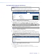
Front Panel Indicators
C
C
C
B
B
B
AXP 64 C AT
INPUTS
OUTPUTS
1
CLIP
SIGNAL
AUDIO EXPANSION PROCESSOR
Extron
2
3
4
1
2
3
4
5
6
CLIP
SIGNAL
A
A
A
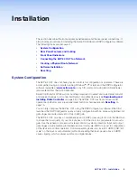
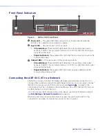
Figure 8.
AXP 64 C AT Front Panel
A
Power LED
— This green LED blinks during boot-up. It lights steadily when the
AXP 64 C AT is powered on and ready to operate.
B
Input LEDs
— One pair for each of the six inputs:
•
Clip indicators:
These red LEDs light when the corresponding input signal
exceeds -3 dBFS. The clip indicator remains on for 200 ms after the input signal
drops below that level.
•
Signal indicators:
These green LEDs light when there is an active source on the
corresponding input.
C
Output LEDs
— One pair for each of the four analog outputs:
•
Clip indicators:
These red LEDs light when the corresponding output signal
exceeds -3 dBFS. The clip indicator remains on for 200 ms after the output signal
drops below that level.
•
Signal indicators:
These green LEDs light when a signal is detected on the
corresponding analog output.
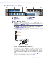
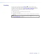
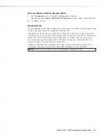
Connecting the AXP 64 C AT to a Network
The AXP 64 supports 100 and 1000 Mbps half duplex and full duplex connections. You
can use either a standard, straight-through Ethernet cable or a crossover cable to connect
the AXP to a network via one of the four AT ports (see
E
, on page 7). The
control device must be connected to the same network. Any one of the four AT ports can
be dedicated as a control connection.
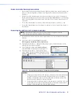
If you do not know the IP address of the control device, use Dante Controller to obtain it
(see
Establishing a Network Connection
When all connections are made and power is applied, the green (activity) LED of the
connected AT port blinks to indicate data activity on the connection.
8
Содержание AXP 64 C AT
Страница 6: ......

