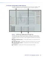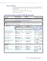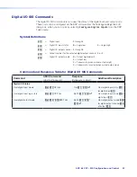
AXP 64 C AT • SIS Configuration and Control
39
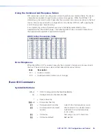
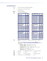
Symbol Definitions
]
or
|
=
CR/LF (carriage return/line feed) (hex
0D
0A
)
}
=
Carriage return (no line feed, hex
0D
)
•
=
Space character
E
or
W
=
Escape key (hex
1B
)
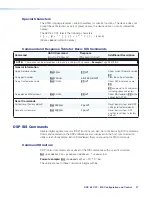
X%
=
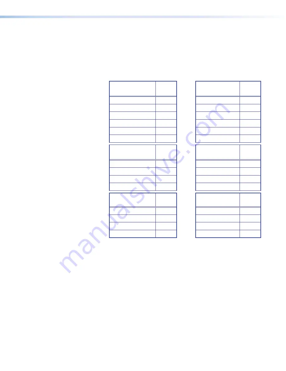
Gain, trim, or attenuation block
Input Gain
X%
Value
AT Output Gain
(Post-processed)
X%
Value
Input 1 gain
40000
Output 1 gain
40100
Input 2 gain
40001
Output 2 gain
40101
Input 3 gain
40002
Output 3 gain
40102
Input 4 gain
40003
Output 4 gain
40103
Input 5 gain
40004
Output 5 gain
40104
Input 6 gain
40005
Output 6 gain
40105
Analog Output
Attenuation
X%
Value
Analog Output
Trim
X%
Value
Input 1 attenuation
60000
Output 1 trim
40100
Input 2 attenuation
60001
Output 2 trim
40101
Input 3 attenuation
60002
Output 3 trim
40102
Input 4 attenuation
60003
Output 4 trim
40105
Analog Output
Attenuation
X%
Value
Analog Output
Trim
X%
Value
Input 1 attenuation
60000
Output 1 trim
40100
Input 2 attenuation
60001
Output 2 trim
40101
Input 3 attenuation
60002
Output 3 trim
40102
Input 4 attenuation
60003
Output 4 trim
40105
X^
=
dB value in 0.1 dB increments, using negative numbers level but not decimal
places.
The valid range depends on the type of block specified for
X%
in the gain
command (see the
Audio Level Control and Processor Selection
commands
on page 89).
•
Input gain,
analog
=
–180
to
800
(–18 to +80 dB)
•
Input gain, digital
=
–180
to
240
(–18 to +24.0 dB)
•
Output gain
(post-processed) =
–1000
to
120
(–100 to +12 dB)
•
Trim
(analog) =
–120
to
120
(-12 to +12)
•
Attenuation
(analog) =
–1000
to
0
(-100 to 0)
X&
=
Mute status
0
= unmute (pass signal)
1
= mute (block signal)
X*
=
Input type
0
= analog
1
= digital
X(
=
Polarity
0
= positive (standard)
1
= negative (inverted)
X1)
=
Phantom power
0
= off (standard power)
1
= on
Содержание AXP 64 C AT
Страница 6: ......

