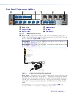
AXP 64 C AT • Installation
8
ATTENTION:
•
Always use a power supply provided by or specified by Extron. Use of an
unauthorized power supply voids all regulatory compliance certification and
may cause damage to the supply and the end product.
•
Utilisez toujours une source d’alimentation fournie par Extron. L’utilisation d’une
source d’alimentation non autorisée annule toute conformité réglementaire et
peut endommager la source d’alimentation ainsi que l’unité.
•
Unless otherwise stated, the AC/DC adapters are not suitable for use in air
handling spaces or in wall cavities. The power supply is to be located within the
same vicinity as the Extron AV processing equipment in an ordinary location,
Pollution Degree 2, secured to the equipment rack within the dedicated closet,
podium, or desk.
•
Sauf mention contraire, les adaptateurs AC/DC ne sont pas appropriés pour
une utilisation dans les espaces d’aération ou dans les cavités murales. La
source d’alimentation doit être située à proximité de l’équipement de traitement
audiovisuel dans un endroit ordinaire, avec un degré 2 de pollution, fixé à un
équipement de rack à l’intérieur d’un placard, d’une estrade, ou d’un bureau.
•
The installation must always be in accordance with the applicable provisions of
National Electrical Code ANSI/NFPA 70, article 725 and the Canadian Electrical
Code part 1, section 16. The power supply shall not be permanently fixed to
building structure or similar structure.
•
Cette installation doit toujours être en accord avec les mesures qui s’applique
au National Electrical Code ANSI/NFPA 70, article 725, et au Canadian
Electrical Code, partie 1, section 16. La source d’alimentation ne devra pas
être fixée de façon permanente à une structure de bâtiment ou à une structure
similaire.
B
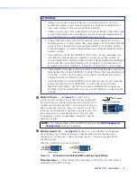
Digital I/O ports
4-pole, 3.5 mm captive screw connectors associated with
the mic/line inputs provide digital input and output ports to
connect microphones with logic circuits. Each has an input
(IN), a ground (G), and two output (O1 and O2) ports. The
input port can enable mic mute from a remote source. The
two output ports can provide tally back to the mic LEDs
to indicate mic status. To wire these connectors, see the
illustration at right.
Do not tin the wires!
(5 mm) MAX.
3 "
16
IN
G
O1
O2
Digital I/O Wiring
NOTE:
To configure these ports, use DSP Configurator (see
C
Mic/Line inputs 1-6
) Connect up to six balanced or unbalanced
microphone or mono line level devices to these 3-pole, 3.5 mm captive screw
connectors for analog mic or line audio input. Inputs 1 through 4 provide 48 volts
phantom power.
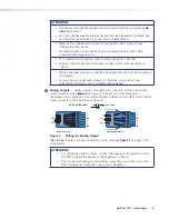
Wire the connectors as shown in figure 5.
Balanced Input
Tip
Sleeve
Ring
Tip
Sleeve
Unbalanced Input
Figure 5.
Balanced or Unbalanced Mic and Line Input Wiring
Phantom power
— Power through the signal lines of the first four mic/line inputs is
selectable via the DSP software.
5
Содержание AXP 64 C AT
Страница 6: ......

