


16
| Tritex
®
TTX Series DC Actuator Installation & Maintenance Instructions
Curtiss-Wright | Rev D | PN75667 | 8/1/22
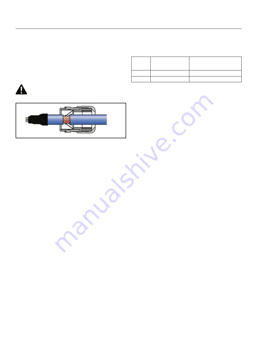
The connectors and cables supplied by Curtiss-Wright properly
terminate shields. If cable glands are used, make sure the
cable gland has a feature to make contact between the metal
body and shield and that the outer jacket is removed as
recommended by gland manufacturer and installed according to
manufacturer instructions. Example shown in diagram below. A
shield connection such as the one shown does not qualify as a
PE connection.
CAUTION!
Avoid Loose Conductive Material
Always apply tape or heat shrink to the end of the shield to
than rated voltage results in proportionally reduced maximum
speed. Refer to Torque/Speed diagrams in catalog for additional
information.
Actuator
Size
Input Voltage (Volts DC)
Rated Continuous Input Current
(Amps)
60 mm
12 to 48 ±10%
18.0
80 mm
12 to 48 ±10%
18.0
4.5 OVER TEMPERATURE PROTECTION
UL/CSA approved motor over temperature sensing is not
provided by the actuator. Motor over temperature protection
relies on limiting maximum current to the motor and if time-
averaged motor current exceeds a continuous current setting,
the actuator trips or faults and disables the drive indicating a
Continuous Current fault. The continuous current fault level is
set at the factory and cannot be adjusted. These limits are set
to keep the stator below 130 ⁰C while in a stall condition at
40 ⁰C ambient.
The motor contains a temperature sensor embedded in the
stator windings to provide an actual temperature indication.
The actuator trips or faults when the temperature reaches
130 ⁰C and disables the drive indicating an Actuator Over-
temperature fault.
Additional over temperature protection is provided by a sensor
in the drive electronics which generates a fault when the board
reaches 110 ⁰C.
Though some fault conditions may be configured to take action
other than to disable the actuator immediately, reconfiguration
of these two faults is not allowed in order to protect the actuator
motor and electronics.
4.6 I/O POWER SUPPLY
An external I/O Power Supply must be used to provide power
for digital inputs, digital outputs, and the optional holding brake,
if present. On DC models of Tritex TTX actuators, logic power
is not associated with I/O power and there is no internal 24 Vdc
supply from main DC (motor) power, making them significantly
different from AC powered models. The I/O power supply must
have the negative side connected to ground and the positive
side fused at 2 A unless internally limited to 3 A or less. The
I/O power supply is typically 24 Vdc nominal, but other nominal
prevent strands of the braided shield from breaking off and
shorting internal electronics or compromising spacing.
Figure 12
–
Example of a shielding type cable gland.
An Ethernet cable is not required to be shielded, or if shielded,
does not require that the shield is connected at the actuator
end. Do not use a shielded RJ45 jack for an internal connection
to this actuator.
4.3.2 Other Grounding Considerations
Extra-low voltage DC power supplies for I/O circuits or a holding
brake must be ground referenced on the negative side to
prevent stacking voltages where there is more than one source.
Avoid use of independent “Instrument Ground” connections. All
ground connections must run back to a single point.
It is recommended that driven parts are connected to
stationary parts of the machine with grounding jumpers. Some
applications produce static electric charges in the moving parts
of a machine, for example plastic molding, that produce static
charges or impulses that exceed those in EMC tests.
4.4 DC INPUT POWER
4.4.1 Input Power Ratings
The following table shows rated input voltage and current. The
maximum voltage applied to the Tritex TTX080 terminals must
not exceed 53 Vdc from bus to Common and Common must
be tied to PE near or at the power source. Operation on less


