EVGA Z690 CLASSIFIED (121-AL-E698)
- 31 -
2. Steps For Installing M.2 Devices
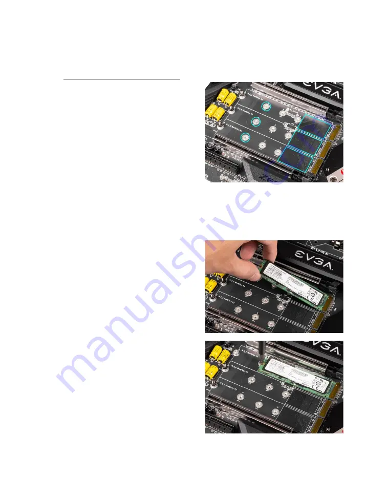
After removing the M.2 heatsink covers,
you will notice that each M.2 slot has three
sets of 110mm retention standoffs – one
for each M.2 slot (with a pre-installed
screw). If your M.2 device requires the full
length of any of these slots, you will need
to remove the pre-attached screw from the
retention standoff. You do not need to
remove the retention standoff.
Before installing your M.2 device, add a thermal pad to the rectangular area, as shown in
the image above. If your M.2 device is 80mm or shorter, you will need to place a
retention standoff (included with your accessories) at the appropriate length (an 80mm
device, for example, would require the retention standoff placed in the circled area
above).
Next, install your M.2 device. Insert the
M.2 device at a slight angle of
approximately 45 degrees to the board.
This will allow the contacts (colloquially
called “Gold Fingers”) to seat completely
into the slot. If the device is fully seated,
you should be able to release it and the
device will rest at an angle of about 30
degrees or lower on its own.
Gently push the M.2 device down on the
raised end. There will be some tension -
this is normal - then use the screw you
removed in Step 1 to secure the device.
At right, you can see that the contacts will
be nearly invisible when the device is
properly seated and the copper mounting
semi-circle is partially visible around the
screw.


