background image

HDSD9545DLY - PRO Profanity Bypass Delay Manual           


Page 3-14

 Revision 

1.3.7 

OPERATION 

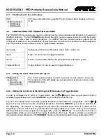
3.10.2. Setting up the Video Reference 

VIDEO 


Video Reference 


ref:ntsc/59.94 
ref:625i/50 
ref:1080i/59.94 
ref:1080i/50 
ref:720p/59.94 


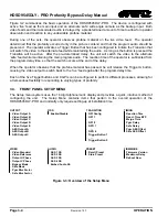
For proper timing of the video and audio signals an analog video genlock 
reference must be supplied.  The HDSD9545DLY-PRO can accept NTSC 
(525i/59.94)  or Tri-level sync HD video references. 
 
In general, the reference video should be chosen to match the standard of 
the video program material passing through the unit.   
 
For SD program video, a standard definition reference video signal must be 
used. 
 
For HD program video, a standard definition reference video signal can be 
used as long as it is at the same frame rate. 
 
e.g.  

HDSDI PGM Video 

Analog Genlock Video 

 1080i/59.94 

525i/59.94 


1080i/59.94 

 
 720p/59.94 


525i/59.94 


720p/59.94 


3.10.3. Setting Up the Video Output Timing 

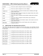
The output stage of the HDSD9545DLY-PRO contains a frame buffer and a line buffer so that the output 
video can be timed with respect to the reference video applied to the 

VIDEO REF

 input BNC.   


!


The  Output V and  Output H phase  adjustments are REAL TIME ADJUSTMENTS 
and will affect the output video timing immediately.  These settings should not be 
adjusted when the output video is in the broadcast chain. 


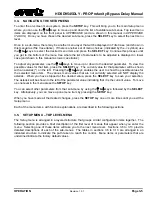
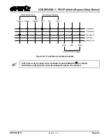
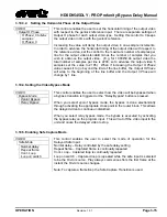
3.10.3.1.  Setting the Vertical Phase of the Output Video 

VIDEO 


Output V Phase 


V Phase: 0 to Max 
Lines 
V Phase: 0 


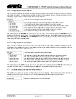
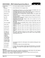
This control enables the user to set the vertical timing of the output video 
with respect to the genlock reference input.  There are separate settings of 
V phase offset for each output video type.  Setting this control to 1 keeps 
the output video in time with the genlock reference. 
 
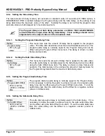
Increasing the value will delay the output video in one-line increments of the 
output video standard.  In order to advance the vertical timing of the output 
video with respect to the genlock reference, set the control to the maximum 
total number of lines of the output video minus the number of lines that you 
wish to advance the output video.  (E.g. for 1080i/59.94 output video the 
total number of lines is 1125, so to advance the output video 5 lines set the 
value to 1120.)  When if increasing the 

Output V Phase

 value causes it to 

go beyond the limit of the frame buffer, the 

Output V Phase

 will wrap to the 

beginning of the frame buffer resulting in a change of one frame of 
throughput delay between the video input and the video output.   


Содержание HDSD9545DLY-PRO

Страница 1: ...ry 2011 The material contained in this manual consists of information that is the property of Evertz Microsystems and is intended solely for the use of purchasers of the Profanity Bypass Delay System Evertz Microsystems expressly prohibits the use of this manual for any purpose other than the operation of these units All rights reserved No part of this publication may be reproduced without the exp...

Страница 2: ......

Страница 3: ...rd grounding prong The wide blade or the third prong are provided for your safety If the provided plug does not fit into your outlet consult an electrician for replacement of the obsolete outlet Protect the power cord from being walked on or pinched particularly at plugs convenience receptacles and the point where they exit from the apparatus Only use attachments accessories specified by the manuf...

Страница 4: ...ely to cause harmful interference in which case the user will be required to correct the interference at his own expense INFORMATION TO USERS IN THE U S A NOTE FCC CLASS A DIGITAL DEVICE OR PERIPHERAL This equipment has been tested and found to comply with the limits for a Class A digital device pursuant to Part 15 of the FCC Rules These limits are designed to provide reasonable protection against...

Страница 5: ... a User Preset section Sept 2010 1 3 7 Added note regarding on air path to overview section Feb 2011 Information contained in this manual is believed to be accurate and reliable However Evertz assumes no responsibility for the use thereof nor for the rights of third parties which may be affected in any way by the use thereof Any representations in this document concerning performance of Evertz pro...

Страница 6: ...HDSD9545DLY PRO Profanity Bypass Delay Manual Revision 1 3 7 REVISION HISTORY This page left intentionally blank ...

Страница 7: ... 2 6 2 5 CONNECTING THE AUDIO 2 6 2 5 1 Connecting Program Live Audio 2 6 2 5 2 Connecting Backup Safe Audio 2 6 2 5 3 Connecting the Audio Outputs 2 6 2 6 CONNECTING TO AN ETHERNET NETWORK 2 7 2 7 CONNECTING THE GENERAL PURPOSE INPUTS AND OUTPUTS 2 8 2 7 1 Connecting the General Purpose Inputs 2 8 2 7 2 Connecting the General Purpose Outputs 2 10 3 OPERATION 3 1 3 1 OVERVIEW OF THE FRONT PANEL DI...

Страница 8: ...g the Horizontal Phase of the Output Video 3 15 3 10 4 Setting the Video Bypass Mode 3 15 3 10 5 Enabling Safe Capture Mode 3 15 3 10 6 Setting the Amount of Blur on the Program Delayed Video 3 16 3 10 7 Setting the Amount of Blur on the Safe Delayed Video 3 16 3 11 CONFIGURING THE AUDIO 3 16 3 11 1 Enabling the AES Audio SoftSwitch for Clean Audio Switches 3 17 3 11 2 Enabling the Embedded Audio ...

Страница 9: ...Step 2 Invoke Upload Mode from the Terminal Program 4 9 4 3 2 3 Step 3 Uploading the New Firmware 4 9 4 3 2 4 Step 4 Completing the Upgrade 4 10 Figures Figure 1 1 Standard Delay Unit Block Diagram 1 2 Figure 1 2 Delay Unit with HD40 option Embedded Audio Mode Block Diagram 1 2 Figure 2 1 Rear Panel Layout 2 1 Figure 2 2 General Purpose I O Schematic 2 9 Figure 2 3 Powering the General Purpose Inp...

Страница 10: ...HDSD9545DLY PRO Profanity Bypass Delay Manual iv Revision 1 3 7 CONTENTS This page left intentionally blank ...

Страница 11: ...IEW Revision 1 3 7 CHAPTER 1 OVERVIEW TABLE OF CONTENTS 1 OVERVIEW 1 1 1 1 HOW TO USE THIS MANUAL 1 3 1 2 GLOSSARY 1 3 Figures Figure 1 1 Standard Delay Unit Block Diagram 1 2 Figure 1 2 Delay Unit with HD40 option Embedded Audio Mode Block Diagram 1 2 ...

Страница 12: ...HDSD9545DLY PRO Profanity Bypass Delay Manual Revision 1 3 7 OVERVIEW This page left intentionally blank ...

Страница 13: ...e output can be returned to the main detailed image without the audience noticing that an edit has occurred On the standard unit the delay can be adjusted up to a maximum of 24 seconds for HDTV or SDTV The user can allocate this maximum delay to primary and secondary paths Typically it is set for max 12 seconds primary and max 12 seconds secondary When the HD40 option is added the delay can be adj...

Страница 14: ... switch DARS Genlock Relay Bypass 2x1 AES Switch with Audio Softswitch ADJUSTABLE DELAY ADJUSTABLE DELAY Live Program Audio 4 AES Dolby E Safe Audio 4 AES Dolby E Hard Mute Pass Hard Mute Pass Output Config Audio Output A AES 1 4 Bypass Protected 4 4 Audio Output B AES 1 4 Audio Output C AES 1 4 4 4 4 Hard Mute Pass 4 Figure 1 1 Standard Delay Unit Block Diagram Video ADJUSTABLE DELAY Embedded Aud...

Страница 15: ...al Chapter 2 provides a detailed description of the rear panel connectors and how the unit should be connected into your system Chapter 3 provides a detailed description of the operation of the front panel controls starting with an overview of the pushbuttons and front panel indicators Chapter 4 provides the specifications instructions on how to update the firmware in the unit and other technical ...

Страница 16: ...ed levels of a pixel BIT PARALLEL Byte wise transmission of digital video down a multi conductor cable where each pair of wires carries a single bit This standard is covered under SMPTE 125M EBU 3267 E and CCIR 656 BIT SERIAL Bit wise transmission of digital video down a single conductor such as coaxial cable May also be sent through fibre optics This standard is covered under SMPTE 259M and CCIR ...

Страница 17: ...ormation D1 A component digital video recording format that uses data which conforms to the CCIR 601 standard Records on 19 mm magnetic tape often used incorrectly to refer to component digital video D2 A composite digital video recording format that uses data which conforms to SMPTE 244M Records on 19 mm magnetic tape often used incorrectly to refer to composite digital video D3 A composite digit...

Страница 18: ... of Motion Picture and Television Engineers A professional organization that recommends standards for the film and television industries SMPTE 125M The SMPTE standard for bit parallel digital interface for component video signals SMPTE 125M defines the parameters required to generate and distribute component video signals on a parallel interface SMPTE 244M The SMPTE standard for bit parallel digit...

Страница 19: ...ctions 2 4 2 2 MOUNTING 2 4 2 3 POWER REQUIREMENTS 2 4 2 4 CONNECTING THE VIDEO 2 5 2 4 1 Video Inputs 2 5 2 4 2 Video Outputs 2 5 2 4 3 Video Timing Reference 2 6 2 5 CONNECTING THE AUDIO 2 6 2 5 1 Connecting Program Live Audio 2 6 2 5 2 Connecting Backup Safe Audio 2 6 2 5 3 Connecting the Audio Outputs 2 6 2 6 CONNECTING TO AN ETHERNET NETWORK 2 7 Figures Figure 2 1 Rear Panel Layout 2 1 Tables...

Страница 20: ...HDSD9545DLY PRO Profanity Bypass Delay Manual Revision 1 3 7 INSTALLATION This page left intentionally blank ...

Страница 21: ...output will be a direct relay connection to the INPUT A BNC INPUT B This BNC connector is for connecting the safe program signal The input can accommodate HD or SD serial digital component video signal compatible with the SMPTE 259M C and SMPTE 292M standards The Video Standard menu item in the VIDEO CONFIG menu is used to select the input video standard OUTPUT A These output BNC connectors are no...

Страница 22: ...PUT A BNCs The bypass relays will activate in the event of power loss to the unit and can also be activated from the front panel or a GPI AES 1 AES 2 AES 3 AES 4 INPUT B These 4 input BNC connectors typically provide inputs for the 4 AES pairs of safe audio associated with the video connected to the INPUT B video input AES 1 AES 2 AES 3 AES 4 OUTPUT A These 4 BNC connectors provide outputs for the...

Страница 23: ...r provides 8 General Purpose Opto isolated inputs GPIs and 4 General Purpose isolated relay outputs GPOs Vint provides 5Volts from the unit and Vext is used to provide external power to the opto isolators Typically Vint and Vext are connected together so that the isolators may be powered from the unit Table 2 2 shows the pin definitions of the GPIO connector Figure 2 2 shows a schematic of the GPI...

Страница 24: ... 03 Common contact 23 GPO 04 NC General Purpose Output 04 Normally closed contact 24 GPO 04 C General Purpose Output 04 Common contact 25 GND Unit Chassis ground Table 2 2 GPI O Port Pin Definitions 2 1 6 Power Connections The main unit has one or two universal voltage power supplies that operate on 100 to 240 Volts 50 60 Hz AC 2 2 MOUNTING The HDSD9545DLY PRO is equipped with rack mounting angles...

Страница 25: ...720p 59 94 1280 x 720 59 94 60 1 001 P 296M 1080i 59 94 720p 59 94 Table 2 3 Video Input Formats 2 4 2 Video Outputs The video output from the five serial digital video outputs is configured at the factory to meet the most common use of the HDSD9545DLY PRO however these outputs can be configured using the OUTPUT CONFIG MENU items In addition to the default signals provided at the outputs both the ...

Страница 26: ...gram audio to the AES inputs 2 5 2 Connecting Backup Safe Audio If you are using discrete AES program audio connect up to 4 pairs of AES audio that is associated with the program video input connected to the INPUT B BNC to the AES 1 B AES 2 B AES 3 B and AES 4 B audio inputs If you are using embedded backup audio then you do not need to connect any program audio to the AES inputs 2 5 3 Connecting ...

Страница 27: ...ite Blue Not used required 6 Receive Orange White or Orange Green White or Green X 7 N A White Brown White Brown Not used required Pin 1 8 N A Brown White or Brown Brown White or Brown Not used required Table 2 4 Standard RJ45 Wiring Color Codes Note the following cabling information for this wiring guide Only two pairs of wires are used in the 8 pin RJ 45 connector to carry Ethernet signals Even ...

Страница 28: ...on is in Figure 2 2 The GPIs are opto isolated inputs that can be powered from an external source or from the frame The GPOs are relay contacts that are normally closed when the power to the HDSD9545DLY PRO is off 2 7 1 Connecting the General Purpose Inputs The GPI s are used as additional triggers to initiate a transition such as a video and or audio switch They can be programmed using the TRANSI...

Страница 29: ... 15 16 5 VDC 4 7 K Vext GND 1 to internal circuit 220 Ohm to internal circuit 220 Ohm 4 7 K GPI 1 Vint 18 17 GPO1 NC GPO1 Common 24 23 GPO4 NC GPO4 Common 25 from internal circuit from internal circuit NC Normally Closed with power Off GPI 8 8 Figure 2 2 General Purpose I O Schematic ...

Страница 30: ...15 25 5 50 VDC GPI Command to internal circuit 220 Ohm GND Vext 2 7 K Figure 2 4 Powering the General Purpose Input Opto Isolators from an External Power Supply 2 7 2 Connecting the General Purpose Outputs The Programmable GPOs are used to trigger external devices and a transition tally capability The GPOs will be in the de energized state when the power is off so all contacts will be closed When ...

Страница 31: ...ing the Operator Reaction Time 3 11 3 9 2 Setting the Reaction Time Bypass 3 11 3 9 3 Setting the Merge Time 3 11 3 9 4 Setting the Video Delay Time 3 12 3 9 4 1 Setting the Program Video Delay Time 3 12 3 9 4 2 Setting the Safe Video Delay Time 3 12 3 9 5 Setting the Program Audio Delay Time 3 12 3 9 6 Setting the Safe Audio Delay Time 3 12 3 10 CONFIGURING THE VIDEO 3 13 3 10 1 Setting the Video...

Страница 32: ...tion to a User Preset 3 18 3 13 MANAGING THE FIRMWARE 3 18 3 13 1 Viewing the Firmware Version 3 19 3 13 2 Viewing the Maximum Delay 3 19 3 13 3 Updating the Firmware Version 3 19 Figures Figure 3 1 Front Panel Layout 3 1 Figure 3 2 Operational Overview 3 3 Figure 3 3 Overview of the Setup Menu 3 4 Figure 3 4 Transition Activation Example 3 9 ...

Страница 33: ...ed image without the audience noticing that an edit has occurred The HDSD9545DLY PRO electronics is housed in a 2RU rack mount frame and is controlled from the built in front panel controls All units can also be controlled by contact closures on the GPI O control port 3 1 OVERVIEW OF THE FRONT PANEL DISPLAY AND CONTROLS Figure 3 1 Front Panel Layout 3 1 1 Trigger Key Group Trigger 1 to 5 These fiv...

Страница 34: ... to back out of menu selections to the next higher menu level or to exit the Setup menu completely SELECT This button is used to choose a sub menu and navigate to the next level down in the menu structure It is also used to make a menu choice The arrow keys are used to navigate through various menu choices at a menu level in the Setup menu 3 1 4 Front Panel Display Messages In addition to the norm...

Страница 35: ...Reaction Time 5 Output Switches to Safe feed High Button Activation 4 Trigger Button RELEASED Activation Reaction Time High Button Activation Time to Switch back from safe Feed Tdelay Fixed Safety Margin 6 Mux Switches back to PGM Upstream Video Path HDSD9545DLY PRO HDSD945DLY PRO Demark Point Safe Feed Live Feed Safe Feed Live Feed Safe Feed Live Feed Safe Feed Live Feed Safe Feed Live Feed Safe ...

Страница 36: ...urs at the end of the delay When the operator observes that the profane material has passed he will release the Trigger A button causing the video output to switch back to the live feed again after the program delay time Each of the five Trigger buttons and 8 GPIs can be configured to perform different processes allowing for a tremendous flexibility in responding to varying types of profanity 3 3 ...

Страница 37: ...t Pressing the keys enables the user to show the possible values for the selected menu item The various menu values that are not currently selected will NOT display the asterisk When you have stopped at the desired value press the SELECT key to save your selection The asterisk will be shown to the left of the parameter value indicating that it is the current value To move up one level in the menu ...

Страница 38: ... This menu is used to view the current firmware version and to upload new firmware into the unit 3 6 CONFIGURING THE VIDEO AND AUDIO OUTPUTS The OUTPUT menu items are used to configure the video and audio outputs The chart below shows the items available in the OUTPUT menu Sections 3 6 1 to 3 6 2 provide detailed information about each of the sub menus Video Output A Configures what video will be ...

Страница 39: ...l for OUTPUT D and OUTPUT E is the quad split quad split output showing the two video inputs and their delayed feeds 3 6 2 Configuring the Audio Outputs There are three identical menu items used to select the function of the AES A AES B and AES C outputs Configuring the outputs for each of the buses is done in the same manner but for simplicity only the AES A menu will be shown in the manual OUTPU...

Страница 40: ...ing the Active State of the GPI Inputs TRANSITION Gpi Config Gpi active low Gpi active high This control selects whether the GPI inputs will be active high or active low The functions of the GPI inputs are set using the Gpi menu items on the TRANSITION menu 3 8 2 Setting the Functions of the GPI Input GPO Outputs and Trigger Buttons In order to configure a GPI GPO or Trigger Button use the keys to...

Страница 41: ...ansition Transition N Trigger 1 Trigger Trigger 5 GPI 1 GPI GPI 8 Front Pannel Buttons External Input Triggers External Output Triggers GPO 1 GPO GPO 4 Figure 3 4 Transition Activation Example Soft mutes only function when embedded audio SoftSwitch is enabled Hard mutes only function when the delayed sources are selected ...

Страница 42: ... video by the amount set by the Safe Blur Factor menu item Immediately switches the on air audio from the Program AES to the Safe AES audio Immediately fades the embedded audio to silence Select the group and channel to be muted Immediately fades the on air AES audio to silence Select the pair to be muted Immediately mutes the audio on the AES A outputs Select the pair to be muted Immediately mute...

Страница 43: ...hear the profanity and activate the appropriate trigger button or GPI The delay is shown in video frames and seconds 3 9 2 Setting the Reaction Time Bypass TIMING React Time BYP ON OFF When React Time BYP is set to on reaction time will be bypassed while switching from safe to program as requested below When React Time BYP is set to off reaction time will be used while switching from safe to progr...

Страница 44: ...econds 3 9 4 2 Setting the Safe Video Delay Time TIMING Safe Delay Sd xxf y yys 4 sec This menu item sets the amount of delay that is applied to the safe video The safe audio delay is normally equal to the Safe Delay but can be offset using the Safe Offset menu item The delay is shown in video frames and seconds The total memory in the unit less the amount of memory taken for the Program Delay det...

Страница 45: ... reference video standard Output H Phase Sets the video output horizontal phase with respect to the reference video Output V Phase Sets the video output vertical phase with respect to the reference video Bypass Mode Selects the video bypass mode Safe Mode Selects the Mode of Operation for the Safe Input Pgm Blur Factor Selects the amount of video blur on the program delayed video path Safe Blur Fa...

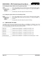
Страница 46: ...adjustments are REAL TIME ADJUSTMENTS and will affect the output video timing immediately These settings should not be adjusted when the output video is in the broadcast chain 3 10 3 1 Setting the Vertical Phase of the Output Video VIDEO Output V Phase V Phase 0 to Max Lines V Phase 0 This control enables the user to set the vertical timing of the output video with respect to the genlock reference...

Страница 47: ...e beginning of the line buffer and the Output V Phase will change by 1 line 3 10 4 Setting the Video Bypass Mode VIDEO Bypass Mode Xpoint Bypass Relay Bypass This control enables the user to select how the video will be bypassed when a bypass transition is triggered or the Relay Bypass button is pressed When you select xpoint bypass mode the bypass is done electronically through activating the app...

Страница 48: ...lied to the delayed safe video when the safe blur or t safe blur transition is selected Increasing the value will increase the amount of blurring 3 11 CONFIGURING THE AUDIO The AUDIO menus are used to configure the audio reference and SoftSwitch settings for each of the audio channel pairs The chart below shows the items available in the AUDIO menu Sections 3 11 1 to 3 11 2 provide detailed inform...

Страница 49: ...n Audio Switches AUDIO Embed Audio SS Emb Aud SS off Emb Aud SS on This menu allows the user to control Audio SoftSwitch on the Embedded audio all groups When SoftSwitch is On the unit will provide a clean audio switch When using non pcm embedded audio such as Dolby E set the embedded SoftSwitch to Off Select Off to disable SoftSwitch Embedded audio switches may pop Select On to enable SoftSwitch ...

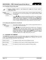
Страница 50: ...e Preset 1 to 10 This control is used to save the values of all the programmable features in the unit in one of ten user presets Use the or keys to select the preset that you want to save Pressing the SELECT key when Store x where x preset 1 10 is shown immediately overwrites the values currently saved in the user preset and reverts up one level to Store Preset To proceed press the SELECT key one ...

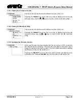
Страница 51: ...sec This menu item is used to view the firmware version of the unit Pressing the SELECT key when this menu item is displayed will show the maximum delay Use the or keys to view the HD and SD maximum delay 3 13 3 Updating the Firmware Version FIRMWARE Reboot Now After new firmware has been loaded into the unit using an FTP connection the unit will require rebooting This menu item provides a conveni...

Страница 52: ...HDSD9545DLY PRO Profanity Bypass Delay Manual Page 3 20 Revision 1 3 7 OPERATION This page left intentionally blank ...
Страница 53: ...NS 4 3 4 2 1 Changing the Fuses 4 3 4 2 2 JUMPERS 4 4 4 2 2 1 Configuring the Unit for a DARS Reference DARS reference not implemented at the time of writing 4 4 4 2 2 2 Configuring the Module for Firmware Upgrades using the Serial Port Method 4 4 4 3 UPGRADING FIRMWARE 4 4 4 3 1 Upgrading the Firmware using FTP 4 5 4 3 1 1 Step 1 Determine the IP Addresses 4 5 4 3 1 2 Step 2 Establishing a Valid ...

Страница 54: ...HDSD9545DLY PRO Profanity Bypass Delay Manual Revision 1 3 7 TECHNICAL DESCRIPTION This page left intentionally blank ...

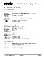
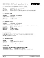
Страница 55: ...f Outputs 5 outputs 2 copies of Output A Input A bypass protected to output A1 Connector BNC per IEC 61169 8 Annex A Signal Level 800mV nominal DC Offset 0V 0 5V Rise and Fall Time HD Video Stds 200ps nominal SD Video Stds 650ps nominal Overshoot 10 of amplitude Wide Band Jitter 0 2 UI Output Return Loss A1 10 dB up to 1 5 Gb s Out A2 B C D E 15 dB up to 1 5 Gb s Output Phase measured with respect...

Страница 56: ... Number of Outputs 3 buses 4 outputs per bus Safe AES Inputs bypass protected to AES A outputs when bypass relay option is installed Connector BNC per IEC 61169 8 Annex A Signal Level 1 v p p Return Loss 35 dB up to 6 MHz Reference From Video Reference 4 1 7 GPI Control Port Number of Inputs 8 opto isolated active high or active low programmable functions Number of Outputs 4 sets of relay contacts...

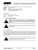
Страница 57: ...ructions in this section of the manual unless you are qualified to do so Make sure that both power cords are disconnected before opening the top cover of the unit 4 2 1 Changing the Fuses The fuse holder is located inside the power entry module To change the fuses disconnect the line cord from the power entry module and pull out the fuse holder from the power entry module using a small screwdriver...

Страница 58: ...tion 4 2 2 2 Configuring the Module for Firmware Upgrades using the Serial Port Method The UPGRADE jumper J12 located at the front of the main circuit card is used when firmware upgrades are being done to the unit using the serial port method For normal operation it should be installed in the RUN position See the section 4 3 2 for more information To upgrade the firmware move Jumper J12 into the U...

Страница 59: ...he user must determine the IP address of the HDSDS9545DLY PRO unit Both the PC laptop and the unit must be on the same subnet for the FTP upgrade to work properly 1 Connect a straight through serial cable to the REMOTE CTL DB9 connector on the rear panel 2 Connect the 9 pin female connector on the end of the serial cable to the PCs RS 232 communications port 3 Start the terminal program 4 Configur...

Страница 60: ...is menu by selecting S The unit ships with DHCP disabled or DHCP enabled set to FALSE If you are not sure whether you should use this option contact your networking IT administrator Once you return to the Main Menu reboot the unit so that the new settings will take effect You can do this using the Reboot Now menu item on the FIRMWARE menu or you can disconnect the power to the unit and then plug i...

Страница 61: ...he FTP prompt type the following put the name of the file bin For example put 9000JJ_SW 1 0b310 bin 17 If the application file is not local to where you are performing the ftp then include the path with the name For example put c firmware 9000JJ_SW 1 0b310 bin 18 A message indicating the successful connection to the module is displayed 19 File transfer occurs in several seconds and the DOS window ...

Страница 62: ...d of upgrading the firmware will take over 15 minutes and is not recommended unless the FTP method fails You will need the following equipment in order to update the Firmware PC with available communications port The communication speed is 115200 baud therefore a 486 PC or better with a 16550 UART based communications port is recommended Straight thru serial extension cable DB9 female to DB9 male ...

Страница 63: ...following is a list of possible reasons for failed communications Defective Serial Upgrade cable Wrong communications port selected in the terminal program Improper port settings in the terminal program Refer to step 5 for settings Note that HyperTerminal will not change port settings while connected Click on HyperTerminal s Disconnect Button then click the Reconnect button to activate changes to ...

Страница 64: ...move and install the module again The supplied bin file is corrupt Wrong file specified to be uploaded Wrong file transfer protocol used make sure you specify Xmodem not Xmodem 1K The PCs RS 232 communications port cannot handle a port speed of 57600 Noise induced into the Serial Upgrade cable 4 3 2 4 Step 4 Completing the Upgrade 14 Power cycle the unit It should proceed through a normal boot up ...

Отзывы: