HDSD9545DLY - PRO Profanity Bypass Delay Manual
INSTALLATION
Revision
1.3.7
Page 2-1
2. INSTALLATION
2.1.
REAR PANEL OVERVIEW
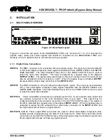
Figure 2-1: Rear Panel Layout
Figure 2-1 shows the rear panel of the HDSD9545DLY-PRO unit. Sections 2.1.1 to 2.1.6 describe the
specific video, audio, and control signals that should be connected to the HDSD9545DLY-PRO unit.
Sections 2.2 to 2.7 describe how to connect them into your system.
2.1.1. Digital Video Connections
INPUT A
This BNC connector is for connecting the live program signal. The input can accommodate HD
or SD serial digital component video signal compatible with the SMPTE 259M-C and SMPTE
292M standards. The V
ideo Standard
menu item in the
VIDEO CONFIG
menu is used to
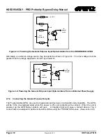
select the input video standard. This input is protected by a bypass relay to the adjacent
OUTPUT A
BNC. The bypass relay will activate in the event of power loss to the unit and can
also be activated from the front panel or a GPI. When the bypass relay is activated,
OUTPUT
A
output will be a direct relay connection to the
INPUT A
BNC.
INPUT B
This BNC connector is for connecting the safe program signal. The input can accommodate
HD or SD serial digital component video signal compatible with the SMPTE 259M-C and
SMPTE 292M standards. The Video Standard menu item in the
VIDEO CONFIG
menu is used
to select the input video standard.
OUTPUT A
These output BNC connectors are normally used for the ‘on-air’ program video output and
are normally connected to the main broadcast chain of your plant. This output may be
configured using the
Video Output A
menu item in the
OUTPUT CONFIG
menu. The output on
the left is protected by a bypass relay to the adjacent
INPUT A
BNC. When the bypass relay is
activated on power loss the output will be a direct relay connection to the
INPUT A
BNC and
the right output will not have any signal present.
OUTPUT B, C, D, E
These output BNC connectors are used for other serial digital component video
outputs and are configured using the
Video Out B,
Video Out C, Video Out D
and
Video Out E
menu items on the
OUTPUT CONFIG
menu. When the bypass relay is activated on power loss
these outputs will normally not have any signal present.
Содержание HDSD9545DLY-PRO
Страница 2: ......
Страница 10: ...HDSD9545DLY PRO Profanity Bypass Delay Manual iv Revision 1 3 7 CONTENTS This page left intentionally blank ...
Страница 12: ...HDSD9545DLY PRO Profanity Bypass Delay Manual Revision 1 3 7 OVERVIEW This page left intentionally blank ...
Страница 20: ...HDSD9545DLY PRO Profanity Bypass Delay Manual Revision 1 3 7 INSTALLATION This page left intentionally blank ...

