Everlast Power i-MIG 353DPi Скачать руководство пользователя страница 29

29


BASIC MIG OPERATION


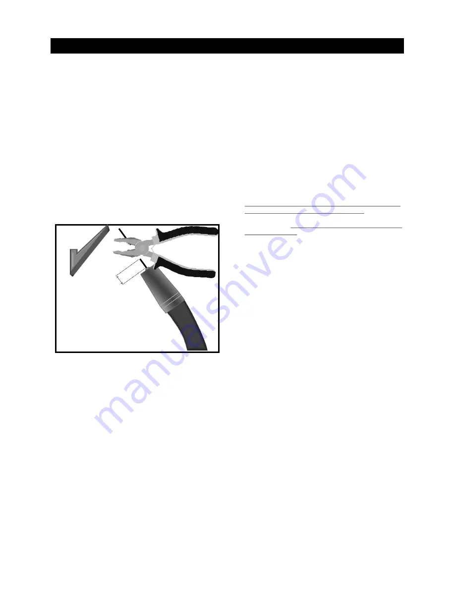
If the burn back control is set too long it can cause the wire to burn 

back into the tip itself and welding of the wire to the tip.  Begin with 

setting the unit for a little less than a quarter second.  If the burn 

back control is set correctly, it will leave about 

1/4”

-

3/8” 

wire stick-

ing out beyond the contact tip.  If a large ball develops on the end 

of the wire, reduce the burn back time so that it creates a balance 

between ball size and stick

-

out.  The short amount of post flow that 

is built into the programming of the Power i

-

MIG helps shield while 

the wire is burning back.  This helps control balling and prevents 

oxidation during burn back. This is a unique feature that is not 

found in many welders with burn back control. Burnback control  

without post flow can cause erratic restarts due to the oxidized or 

over

-

balled wire tip.  


Even with the burn back control properly adjusted,  due to operator 

error, an occasional quick trim of the wire may be necessary for 

best arc starts.  But overall, when used in a production setting or in 

a fabrication shop, the burn back control can save on labor and 

aggravation.


Starting the Arc and Welding.


Starting the arc is a relatively simple process.  Before beginning, 

the wire should initially be trimmed to between 1/4 to 

3/8”.  

Once 

the wire is trimmed, the  gun should be firmly grasped to prevent a 

phenomenon often referred to as 

machine gunning

”.   

A light 

grasp, especially at start, can cause the arc to stutter as the wire 

pushes back on the gun, lengthening the wire stick

-

out and creating 

an irregular start and porous weld.  


The end of the wire should be positioned just barely above the 

metal when the trigger is pulled for the cleanest start. This will 

position the end of the contact tip about  

1/2” 

above the weld. The 

gun should be in the vertical position, with no more than 5 degrees 

lean in either side to side direction.  Holding the wire too far off 

from the metal will result in rough starting and too long of wire stick 

out.    


Once the arc has been established, the gun can then either be 

pushed or pulled in the direction of the weld.  In either case, the 

gun nozzle should be positioned directly over the weld without 

angling the wire to one side or the other of the weld as already 

mentioned.  The gun should have no more than 15 degrees lean 

pointed into (push) or pointed away from (pull) the direction of 

travel.   In most cases a push motion is desired.  However, a lot of 

texts offer conflicting information on whether to push or to pull the 

gun.  In reality, both are correct if used correctly and with each 

having particular strength and weakness.  Either one done with too 

much gun angle will result in undesirable results. Most open

-

minded people who are well versed in MIG  quickly develop a 

sense of when to push and when to pull the gun.   Even for novic-

es, a sense of when to push and pull the gun comes quickly with a 

little practice.  Pushing can result in shallower penetration but the 

molten puddle is easier to see and the arc sits easily on the leading 

edge. It will usually leave a aesthetically pleasing bead.  However,  

be careful to prevent the gun from leaning toward or away from the 

direction of travel too much as spatter will increase and shielding 

gas flow may become turbulent, creating porosity in the weld.  

Pulling will result in deeper penetration, but can result in a narrow 

bead without much side fusion.  It also can leave an undesirable 

humped appearance if not done correctly or if travel is too slow.  

Whenever MIG welding with Aluminum, whether with the standard 

MIG gun or the Spool gun ALWAYS push the gun.  

During Pulse 

Welding, a Push angle is recommended wherever possible, regard-

less of metal type. 

 If using Flux Core, a dragging motion is almost 

always recommended.


Weaving (oscillating the torch from side to side in one pattern or 

the other), particularly a MIG bead, is a topic of controversy as 

much as whether to push or pull the MIG gun.  Stringer beads are 

often best for novice welders.  Stringers are simply straight beads 

that move forward with little or no side to side travel or oscillation.  

These will offer the soundest welds for a beginner.  Stringer welds 

leave little or no room for contaminates to enter the weld and are 

the fastest to produce without creating an opportunity for cold lap.  

Moving too quickly however with a stringer can create undercut 

which will weaken the weld.  The best policy is to move a slow 

steady speed, making sure the sides of the weld are filled.  If under-

cut is present, it is either from too much voltage or moving before 

the wire has time to fill the area the arc has melted.   


Think of weaving as a method of  

sewing

” 

the metal together.  If 

weaving is of interest to you, start with the basic weave pattern.  

Simple weaves using one variation or the other of a cursive 

e

” 

motion are best to begin with.   Other weave patterns can be used 

of course.  C

s, V

S, U

s , Triangles and many more weave patterns 

can be used depending upon the application.  Weaves are em-

ployed for a number of reasons.  Weaves are often considered to 

have a more pleasing appearance and can help bridge gaps where 

fit up is a problem.  A weave is also frequently used to manage heat 

build up.  For example: when welding vertically weaves are almost 

always used to prevent the molten metal from sagging due to the 

force of gravity.  The major drawback of weaving is that it introduc-

es a greater possibility of getting inclusions and other forms of 

contamination in the weld.  Properly done weaving is a valuable 

tool, but it must be practiced before employing it in any structural 

or critical application.


Metal Cleaning.


MIG welding requires a well prepped surface to obtain a sound 

weld. The removal of paint, rust mill scale, or other contaminate 

such as grease should be done before welding.  Stick welding is 

more forgiving of rust and mill scale, but when MIG welding, con-

taminates will result in porosity and inclusions in the weld, weaken-

ing it.  A grinder will usually prep the metal sufficiently to remove 

oxidation and paint.  However, to remove grease, a degreaser such 

as acetone should be used.  Do not use any degreaser such a brake 

Section 2                                                                                  Setup Guide 


1/4”

-

3/8”


(6mm–


9mm)


Содержание Power i-MIG 353DPi

Страница 1: ...fications and Accessories subject to change without notice 380 Swift Ave Unit 12 South San Francisc0 CA 94080 USA Operator s Manual for the Power i MIG 353DPi Safety Setup and General Use Guide A Digi...

Страница 2: ...Feature and Terms 13 Setup Guide 13 Polarity and Gas Selection Guide 14 MIG wire Gun Connection Power Source and Wire Feeder Information 15 Water Cooler Information 20 Rear Panel Features and Connecti...

Страница 3: ...eract with each other Technical advisors are active on the forum daily We also divide our support into two divisions tech nical and welding performance Should you have an issue or question concerning...

Страница 4: ...Support support everlsatwelders com au NOTICE Product Specifications and features are subject to change without notice While every attempt has been made to provide the most accurate and current infor...

Страница 5: ...Support The content of this manual is not meant to be an exhaustive primer on welding It is written to an audience that if not professional will have at least some basic knowledge of welding terms and...

Страница 6: ...nt protective equipment If no protection is available exclude them from the work area Even brief exposure to the rays from the welding arc can damage unprotected eyes Always wear hearing protection be...

Страница 7: ...the eyes nose or throat are signs that you need to increase ventilation Stop immediately and relocate work if necessary until adequate ventilation is obtained Stop work completely and seek medical he...

Страница 8: ...smoke or embers If welding or cutting outside make sure you are in a cleared off area free from dry tender and debris that might start a forest or grass fire Do not weld on tanks drums or barrels tha...

Страница 9: ...Stainless Steel 40XX series Aluminum 50XX series Aluminum and Bronze wires Burn Back Control 01 5 seconds 10 25V Inductance 1 10 in whole number increments Pulse Frequency Single Synergically Controll...

Страница 10: ...nforms to North American electrical standards for welders rated for Single and Three phase commercial service This means the unit does not include a plug since three phase and single phase welder plug...

Страница 11: ...d resume welding output contact Everlast The unit is protected from Over Currents which may cause excessive input or power draw on the machine This can occur from undersized conductors too long of ext...

Страница 12: ...tion for Steel wires Flux core operation is also permissible with the non pulse MIG mode with the synergic function turned off with flux core drive rolls installed as well as steel wires when full man...

Страница 13: ...Once the arc is established the wire feed speed automatically begins to rapidly ramp up to weld at the desired wire speed Amps Note The slow run in feature prevents the operator from taking accurate m...

Страница 14: ...2 For best operation Short Circuit MIG 75 25 Ar CO2 or 100 CO2 MIG GMAW STAINLESS STEEL INOX For Synergic Pulse Spray 98 2 Ar O2 98 2 Ar CO2 For Short Circuit Tri Mix or 98 2 Ar CO2 MIG GMAW ALUMINUM...

Страница 15: ...ffset of the machine discussed later depending upon operating mode See full discussion of setting up and adjusting the unit Amp Control Although this control varies wire speed it also indirectly varie...

Страница 16: ...losed zipper or saw blade This also has a zig zag marking on the side of the drive roll next to the wire diameter marking These drive rolls may be stamped in metric wire sizes or in both metric and im...

Страница 17: ...gn and offers excellent ergonomics and dependability A water cooled Gun capable of sustained higher amperage welding may be purchased from Everlast To load the spool of wire Open the clam shell cover...

Страница 18: ...hreads into the gun section 4 6 5 Reverse the procedure Begin by lowering the upper drive rolls into contact with the lower drive rolls keeping the wire securely held down so that it stays in the inne...

Страница 19: ...ent The If welding flux core gasless the connections will be reversed with the work clamp in the positive terminal and the feeder in the negative terminal The work clamp will be connected directly to...

Страница 20: ...e holes on the top to reattach the mounting rails should they not line up with the rails on the bottom of the 353DPi power source This is done to accommodate multiple Everlast welder models with the s...

Страница 21: ...n before attaching the plug or attempting to wire a new circuit or rewire a new circuit for this welder Refer to Article 630 of the NEC for proper breaker and conductor sizing FUSE Operate on240V 1 Ph...

Страница 22: ...from set voltage to dynamically display actual welding voltage output while welding 3 Amps Display and Warning LEDs The Amps display is a single purpose display and is used only to display selected A...

Страница 23: ...button is used to select the desired welding mode The modes that are selectable are Stick Standard Synergic MIG Steel mode MIG CO2 Single Pulse and Double Pulse modes As the button is pressed each tim...

Страница 24: ...he selected welding mode Note All functions may not appear to be available in 4T special mode due to the welding mode select ed Only certain functions apply to each welding mode See the chart on 2T 4T...

Страница 25: ...more rapid melting of the base metal This portion of the pulse should be set with higher settings than the base part represented by the Welding LED of the Pulse or results will not be satisfactory Th...

Страница 26: ...de This represents the Base stage of the Double Pulse welding mode This is the low Pulse layer of the Double Pulse mode In comparison to the Peak Pulse value in item 4 on this page both Amps and Volts...

Страница 27: ...d so the projected Amp output on the welder can be accurately computed Keep in mind that this is a projected output There are a number of things that can affect the true Amp Volt output of the welder...

Страница 28: ...he arc of one brand over the other since people develop personal preferences in arc perfor mance With that in mind having an adjustable Inductance serves several functions 1 The Inductance allows the...

Страница 29: ...to see and the arc sits easily on the leading edge It will usually leave a aesthetically pleasing bead However be careful to prevent the gun from leaning toward or away from the direction of travel t...

Страница 30: ...s is a primary way to introduce cold lap and incomplete fusion to the weld Single pass welds should not exceed 1 4 even with the heaviest wire the welder is capable of handling A thick pass may also b...

Страница 31: ...a plain open root can be used as a backer plate adds to the time and labor involved A knife edge is also acceptable so long as the joint is fully penetrated when the weld is completed Open root gaps w...

Страница 32: ...es the heat on both sides of the joint and keeps the bead centered Don t confuse this with push or pull angle in the travel direction Correct Technique The gun is angled toward the back of the weld wh...

Страница 33: ...t more Use push technique Characteristics Large convex weld with bulging at toes weld legs exceed thickness of the metal being welded Possible Causes Not enough voltage too much wire speed overfilling...

Страница 34: ...etal actually pinches off before the wire touches the weld puddle During the Axial spray mode the arc should never short circuit Axial spray is accomplished by using higher volts and amps than would b...

Страница 35: ...also tried to simplify operator input without compromising the basics of Synergic operation In Synergic Single Pulse MIG mode the Power i MIG 353DPi can be compared to other types of Synergic single...

Страница 36: ...ermine the approximate wire feed speed amp value After initially set Amps should only be adjusted again after no workable setting for the Voltage Offset or Induct ance has been found Avoid radical cha...

Страница 37: ...tance to 5 and turn up from there If spatter is noticed it can be a product of having the Inductance set at one extreme or the other It also can be from having the Amps set too low Section 2 Setup Gui...

Страница 38: ...4T X X X X X X X 4TSPCL X X X X X X X X Gun Trigger Mode Pre Flow S Hot Start Peak Pulse Inductance Burn Back Volt Offset Burn Back Time S Post Flow Time S End Arc Amps Volt Offset Frequency Hz Pulse...

Страница 39: ...ING HOT START The graphical representation above depicts the motions of the MIG Gun trigger in relation to the welding mode Each movement of the MIG gun trigger signals the unit to start a new phase o...

Страница 40: ...4T Special The graphical representation above depicts the motions of the MIG Gun trigger in relation to the welding mode Each movement of the MIG gun trigger signals the unit to start a new phase of...

Страница 41: ...these settings advance the MIG process button to the Double Pulse MIG function press and hold for up to 5 seconds until the setup button is illuminated and the display changes to read a combina tions...

Страница 42: ...pects that will seem different One of the main ones is that the arc is better controlled in most situations by pushing in when the arc seems to get weak or unstable and the arc force will kick in as t...

Страница 43: ...nce by having too much of a torch angle Start with a 90 degree angle and then lean the gun slightly about 15 degrees to the push position 4 Welding aluminum is not a short circuit process It is a spra...

Страница 44: ...ay result The MIG torch liner may eventually become worn and will need to be replaced When welding aluminum with the main gun a Teflon liner must be used necessitating a liner change A spool gun is th...

Страница 45: ...any other type MIG torch since most manufacturers offer torches with a Euro connector as an option This list is provided as a general cross reference as a courtesy from Trafimet and does not guarante...

Страница 46: ...air or Replace it Control board damaged Check the circuit 9 Intermittent Arc Wandering arc Work Clamp is not secure or it is damaged Too windy breezy Check and or Work Clamp change position of clamp a...

Страница 47: ...47...

Отзывы: