


ENVR8304D-8CH / ENVR8304E-8CH
74
6.2
Record & Playback
You can configure the basic recording settings on the hard disk. You can also configure the
settings for Quick Archive and Quick Playback.
6.2.1
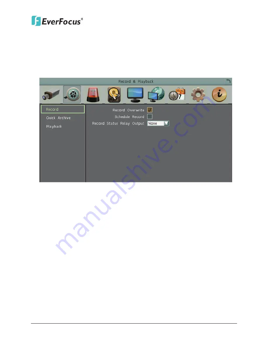
Record
Figure 6-20
Record Overwrite:
Check the box to overwrite the hard disk when it is full. Note that unless
this box is checked, or the NVR will stop recording when the hard disk is full. The use of
record overwrite is strongly recommended. If you do not use this feature, please be sure to
enable the Event setting for Disk Full for notification (see
6.3.4 Other
).
Schedule Record:
Check the box to record by the schedule. Please see
6.7 Schedule
for
more details.
Record Status Relay Output:
Select a number to monitor the recording status of the
selected alarm relay. The recording status of the selected alarm relay will be transmitted to
the alarm output device.
Содержание ENVR8304D
Страница 127: ...ENVR8304D 8CH ENVR8304E 8CH 118 Figure 6 59...


