background image

SigNET 200/300 User Guide  


4  


ELAB 

1543 

1.  Introducing the SigNET 200/300 System 

The SigNET 200/300 system must be installed by a qualified installation engineer. When the installation has been 
completed, the engineer provides users with passwords to set or unset and configure the system as required.  

2.  Using the Keypad 

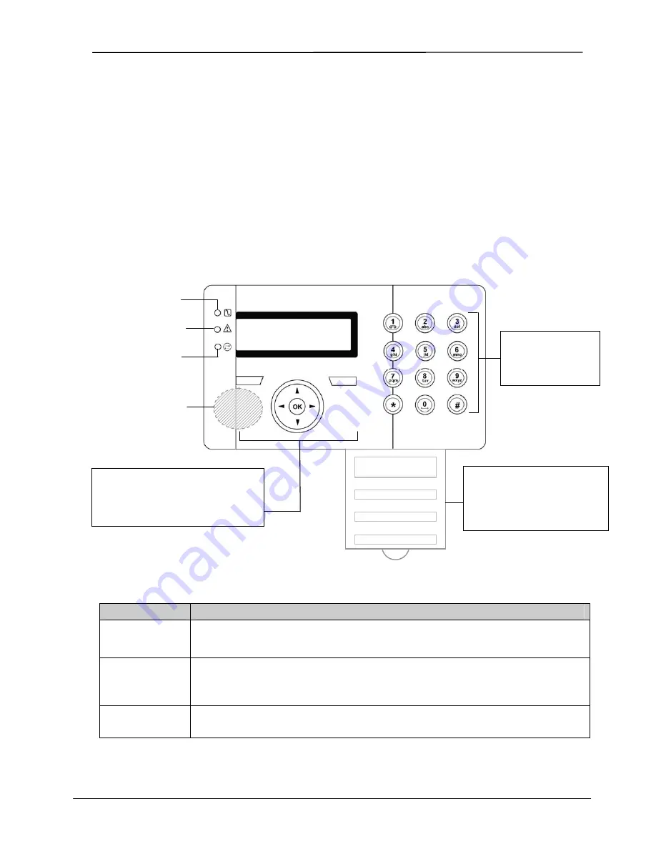
The SigNET Keypad is a wall-mounted programming interface unit that allows users to enter User Programming 
menus (password protected), and to perform operational procedures (arm/disarm) on the system. The Keypad unit 
includes an integral front tamper switch and has a 2 line x 16 character display. Three LEDs provide information on 
AC power, system alerts, and communications status. The Keypad features easy-to-use navigation to assist in 
locating required programming options, and has two context sensitive soft keys (left and right) for selecting the 
required menu or program setting. 

The SigNET Keypad may be factory fitted with a Portable ACE (PACE) proximity device reader and/or a wireless 
module for the enrolment of wireless sensors.  

Figure 1 – SigNET Keypad 


Table 1 – LED Status Indicators 

LED  

Description 

AC Mains LED 
(green)


Indicates presence or failure of the Mains supply 

FLASHING:

 AC Mains fault detected 

STEADY:

 AC Mains OK


System Alert  
(yellow)


Indicates a system alert 

FLASHING:

 System Alert detected; display indicates the location and nature of the alert. If the 

system is SET, no indication of system alerts is given. 

OFF:

 No alert detected 

Comms LED 
(red)


Indicates status of the E-BUS communications when in FULL ENGINEER programming 

Programming Keys 

1 x multi-functional navigation key 
2 x context sensitive programming 
keys (left and right)  

01 MAY 08 17:00 

AC Mains LED 

System Alert LED 

Comms LED 

Keypad 

12 x alphanumeric 
keys for numeric 
and text data entry

Portable ACE 
Receiver Area 

Licence 
Details 

Installer Contact 

Installer Name 

Installation Date 

Pull-down Information Tab 

The installer contact and licence 
details are located on the pull 
down information tab at the rear 
of the unit 

Содержание SigNET200 Series

Страница 1: ...E L A B1 5 4 3 S i g N E T2 0 0 3 0 0S e r i e s U s e r G u i d e...

Страница 2: ...en changing or installing expanders on the SigNET 200 300 system always ensure that all anti static precautions are adhered to while handling connectors wires terminals and PCBs Europlex Technologies...

Страница 3: ...THE SYSTEM 7 3 7 RESTORING AN ALARM ACTIVATION ALERT 7 3 8 CODED RESTORE 8 3 9 USING 868MHZ WIRELESS FOB 8 3 10 USING A PORTABLE ACE 8 3 11 USING X10 FEATURES 9 4 USER MENU OPTIONS 10 4 1 INHIBITING A...

Страница 4: ...NET Keypad may be factory fitted with a Portable ACE PACE proximity device reader and or a wireless module for the enrolment of wireless sensors Figure 1 SigNET Keypad Table 1 LED Status Indicators LE...

Страница 5: ...e down arrow key moves the user to the next programming option in the same menu level Continually press this key to scroll through all programming options available on the current menu level In alphan...

Страница 6: ...buzzer sounds to indicate that the user should exit the building When the system has been fully set the LCD displays FULLSET on the bottom line for approximately 10 seconds If the alarm fails to set...

Страница 7: ...on the Keypad and the Alert LED flashes The Keypad continues to display the alert until the alert is restored 3 7 Restoring an Alarm Activation Alert Alert conditions on the SigNET are indicated on t...

Страница 8: ...digit reset code displays on the top line 4 Provide 6 digit code to installer ARC 5 Receive newly generated code from installer ARC 6 Enter new code at the AUTH CODE prompt 7 Press SELECT The message...

Страница 9: ...a hall light could be configured to turn on when the front door of the house is opened Alternatively the function can be controlled directly at the Keypad X10 settings are programmed by the installati...

Страница 10: ...l to the ISOLATE option and press SELECT right soft key 2 Scroll to the ZONES option and press SELECT right soft key 3 A list of zones on the system displays Select the required zone and toggle the se...

Страница 11: ...Chime Function The chime function can be enabled or disabled on all zones where the chime has been programmed as an audible alert feature To enable or disable the chime function 1 Scroll to the CHIME...

Страница 12: ...ts can be sent to users as SMS messages Alarm Activation Confirmed Alarms Fault and Tamper Arming and Disarming Mode Change Inhibit and Isolate All other types of events 4 9 1 SMS Events To receive Ev...

Страница 13: ...Depending on the SMS authentication configured by the installation engineer the user s mode of SMS may vary If the system SMS Authentication is set to the SMS PIN Code or Caller ID it is necessary to...

Страница 14: ...code followed by either a space or a full stop Where is the code and command is the command command or command For example the command HELP is this text HELP or HELP Table 3 COMMANDS code Using Code U...

Страница 15: ...engineer access 1 Scroll to the GRANT ACCESS option and press SELECT right soft key 2 Select the ALLOW ENGINEER option right soft key and select ENABLED To disallow engineer manufacturer access follo...

Страница 16: ...this mode An exit timer can be applied to this mode by enabling the Partset A timed variable To perform a PARTSET A see Section 3 2 PARTSET B Standard Manager The PARTSET B option applies protection t...

Страница 17: ...e time and date information is accurate these fields are presented in the event log when reporting system events To set date or time see Section 4 3 TEST Standard Manager This menu option provides the...

Страница 18: ...SigNET 200 300 User Guide 18 ELAB 1543 Appendix C Zone Chart Zone Description...

Отзывы: