Eurolube 53430 Скачать руководство пользователя страница 3


LUBE-MASTER R10


3(21) 


1.  Introduction 

The LUBE-Master TSM module, (

T

ank

 Surveillance M

odule), is used to control pumps and/or measure levels in tanks 

using floater based level switches. A TSM can be used both for fresh and waste oil tanks. 
 
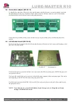
The TSM (53430) is based on a TCM 53408 but has a lid (p/n 203 03 11) with a led indicator board (p/n  203 03 03) 
and a connector adapter (p/n   203 03 17) added to the main board 203 02 91. 
 
Earlier models than serial number 12-02000 can be made with either a MPDM (53400) with another software ( chip 
labeled TSM 1.xx.xx)  and/or have a lid with chassis mounted indicator led’s. Because of this a lot of this manual also 
in most parts covers older modules. Some features may be missing and some default settings may be different. 

NOTE!  

The LUBE-Master installation manual should be available when installing and configuring a 
TSM. 

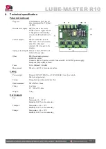
2.  Mechanical installation 

The TSM is delivered mounted in a metal box with power supply. It can also be delivered as a spare part PCB (p/n 203 
03 91) . 
 
Complete TSM in a box is mounted on a wall or other suitable place using the four-ø5 mm holes in the bottom corners 
of the box. 
 
If a PCB is used it is important that a power supply with enough performance is used, 24VBC 5A. 

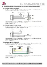
3.  Electric installation 

3.1.  The main module  

The TSM should be connected to mains 230VAC/50Hz using phase, neutral and ground. 

Eurolube recommend that the connection is done through a 2-pole lockable working switch. 

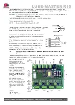
The “knock-out” holes on the lower right hand (see picture) should only be used for mains power supply to separate 
mains from the circuit board (DC) side of the module. 

The TSM is equipped with a switched power supply of 150W that can be set for 110VAC/60Hz or 230VAC/50Hz 
by the internal switch shown by the yellow sticker. 


It has five connectors 

(A)

 for the LUBE-Master communication. Two of these connectors, 

MPDM IN 

and

 MPDM 

OUT

 are not connected to 

+24V

 and are intended for a connection to another TSM, MPDM or other modules that 

already have +24VDC. This is to prevent conn24VDC from two power supplies.  

Содержание 53430

Страница 1: ...English Manual for TSM module 53430 R10 181008 LUBE MASTER R10 R10 TSM MANUAL TANK SURVAILLANCE MODULE 53430 ...

Страница 2: ...ICATION 10 5 5 1 Set tank capacity 10 5 5 2 Set the tank reorder volume level 10 5 5 1 Set the tank stop volume level 11 5 5 2 Set tank bottom area 11 5 5 3 To configure a TSM port for a tank that does not have a constant area 11 5 6 DISPLAYING TANK CONTENT ON A LED DISPLAY 12 5 6 1 Set LED address 12 5 6 2 Set LED update interval 12 5 7 SET THE TYPE OF TANK PC SYSTEM 13 6 MENU TREE 14 7 FAST MENU...

Страница 3: ... with power supply It can also be delivered as a spare part PCB p n 203 03 91 Complete TSM in a box is mounted on a wall or other suitable place using the four ø5 mm holes in the bottom corners of the box If a PCB is used it is important that a power supply with enough performance is used 24VBC 5A 3 Electric installation 3 1 The main module The TSM should be connected to mains 230VAC 50Hz using ph...

Страница 4: ...TSM port is connected to order oil emptying of the level sensor B of a TSM port is connected to Stop level of the level sensor GND of a TSM port is connected to common of the level sensor 24V of a TSM port is connected to one of the terminals of a solenoid valve and Sol is connected to the other TIP If a TSM is used for a tank containing flammable liquid it could be necessary to use an EX protecti...

Страница 5: ...ndicator board mounted in the lid of the module the status of the discrete level sensors and the pump control can be seen from the outside The indicator board is powered by the Port 1 inter connection cable If the board has power 24VDC the power led see picture will be lit The 8 pole SIL switch block can be used to invert the LED output compared to the sensor pump signal This can be used depending...

Страница 6: ...button for 5 seconds to set a temporary address Immediately enter set up mode from a KP and type 0 and then ENTER to get to the Main menu of the TSM see below NOTE Only one new module can be installed at a time If you press the RESET button on several terminals simultaneously or in a sequence only the most recently pressed will be active TIP Follow preferably Recommendation for setting new address...

Страница 7: ...t TCM PortX Tank To set a tank number for a port from the main menu Enter menu TSM PortX by scrolling with or At PortX press ENTER Press ENTER to get the cursor Check the number of the tank that is connected to portX type that number in and press ENTER to acknowledge When the cursor disappears it is finished Press EXIT two times to leave Set Up mode 5 2 Set the Mask TCM PortX Mask Using the Mask e...

Страница 8: ... Offset adjusting is used to obtain 0 volume when the tank is empty If the sensor 53417 is used a normal value is 0 080 The sign is typed on the keypad by first pressing down arrow yellow two times followed by the mark If the tank is empty put the sensor in the tank at the bottom If there is fluid in the tank hold the sensor outside the tank at bottom level Adjust the offset value until the tank l...

Страница 9: ... 5 4 Fluid specification 5 4 1 Set fluid name The fluid name set in the TSM makes it possible to show the fluid name in the info box for the graphic representation of the analogue sensor It should be set to the same value as in the PC database Enter menu TCM PortX by scrolling with or At PortX press ENTER Scroll to FN using or Press ENTER to get the cursor Type the name of the fluid and press ENTE...

Страница 10: ...T two times to leave Set Up mode 5 5 Tank specification 5 5 1 Set tank capacity The tank capacity set in the TSM is used to create a true graphic representation of the analogue sensor status It should be set to the same value as in the PC database Enter menu TCM PortX by scrolling with or At PortX press ENTER Scroll to TankVol using or Press ENTER to get the cursor Type the capacity of the tank an...

Страница 11: ...ank bottom area is only usable for a tank with the same projected area throughout the total tank height For other tank forms the profil has to be downloaded to the TSM from a PC The area should be in square meters When the area is typed in and ENTER is pressed the volume for each step on the scale is calculated and stored in the TSM Enter menu TCM PortX by scrolling with or At PortX press ENTER Sc...

Страница 12: ... LED using or Press ENTER to get the cursor Type the LED address and press ENTER to acknowledge When the cursor disappears it is finished Press EXIT two times to leave Set Up mode 5 6 2 Set LED update interval The default update interval is 1 second but since tanks seldom changes with a speed that needs updating every second it good to increase the interval to free up network for more important th...

Страница 13: ...s of security and redundancy The system must be told what hardware there is and how to use it properly This is done through the Tank Type Tank type is set by a string of 0 and 1 were the first position sets if it is a fresh or waste oil tank The second position tells if there is a discrete level sensor present or not and the third position defines if there is an analogue sensor present or not Tank...

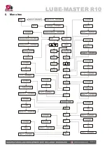
Страница 14: ...LUBE MASTER R10 14 21 6 Menu tree ...

Страница 15: ...Where X is the port number Change Offset 0X03 Where X is the port number Change Calibration 0X04 Where X is the port number Change Density of fluid 0X05 Where X is the port number Change Max volume of tank 0X06 Where X is the port number Change LED Address 0X07 Where X is the port number Change Name of Fluid 0X08 Where X is the port number Change Part number of fluid 0X09 Where X is the port numbe...

Страница 16: ...ith 10 bit A D converters Other RISC based microprocessor EEPROM 64 KB Connector E for 3 pos key switch Connector C for 24 VDC power supply SetupLock jumper H not used Fuses T6 3A D and F1 6A B Max current 500 mA 4x1 25 A for solenoid valves Casing Power supply Primary 230VAC 50Hz 2A or 110VAC 60Hz 3A set by a switch Short circuit protected Casing Strong black powder painted steel box Outer measur...

Страница 17: ...a dispense point is open and the sensor works properly the following connection should be made The TSM port should be set to control the appropriate PC tank in relation to the physical tank Correct TankType TSMAddress and TSMPort should be set using with WinDB Manager Mask 4 TankType 01 9 3 Waste oil tank 53132 2 levels To achieve a proper function that is the pump stops if the physical tank is fu...

Страница 18: ...ensor and the tank module if the liquid is classed as flammable For this purpose the EX barrier 53178 and a special EX approved cable 53164 can be used The EX barrier the solenoid valve that controls the air to the pump and the tank module should be placed outside the EX classed area The EX approved cable should be used to connect the level sensor on the tank inside the EX classed area with the EX...

Страница 19: ... accuracy for tanks with a height of 1 5 meters Max height depends on density of fluid The measuring resolution for a TSM with a 53417 sensor is 4 mm for water and about 4 5 mm for mineral oil Connect the red wire to 24VDC and the black wire to Sense 24VDC and Sense are printed on the PCB If the sensor cable 6 5 m is to short to reach the TSM it can be lengthen using a standard 2 lead wire with co...

Страница 20: ...SMPort should be set using with WinDB Manager MASK TankType 1 12 EX barrier 53188 for analogue sensors An EX barrier is needed between the level sensor and the tank module if the liquid is classed as flammable For this purpose the EX barrier 53188 and a special EX approved cable p n 53164 should be used The EX barrier the solenoid valve that controls the air to the pump and the tank module should ...

Страница 21: ...SM box In a small system or at limited space it is possible to mount an additional module PCB in a TSM In this example a MPDM board is added To do this the TSM PCB has to be moved and turned one quarter of a turn See pictures below Make sure that the TSM is disconnected from the mains power supply and the LUBE Master network before any work is started Use a voltmeter to make sure that there is no ...

Отзывы: