


Instruction Manual ZHK
V07-19.0
85/129
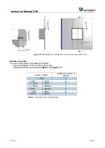
Secondly: By software via controlling. In case of failure contactors immediately cut off the electric
heater from power supply.
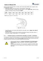
-
The 2 safety thermostats are connected in serial connection.
-
The 2 safety thermostats are equipped with manual reset.
-
After triggering, the reason for stopping must be detected and eliminated before the reset of the
thermostat!
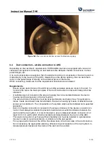
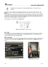
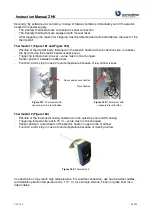
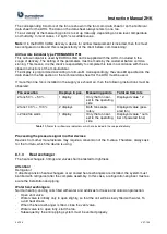
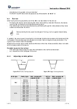
Thermostat 1 (Figure 181 and Figure 182)
-
Position of thermostat body: fastened on the electric heater at the connection side, is accessi-
ble by removing the electric heater access panel.
-
Triggering temperature: pre-set
–
value must not be changed.
-
Sensor position: between heating bars.
-
Function: alarm stop in case of over temperature because of low airflow issues
Figure 181:
Thermostat with
cover cap on the reset button
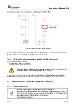
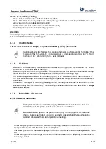
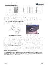
Figure 182:
Thermostat with
uncovered reset button
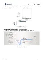
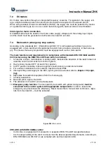
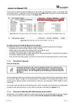
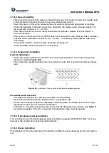
Thermostat 2 (Figure 183)
-
Position of the thermostat casing: fastened on the outside panel of AHU casing
-
Triggering temperature: set to 70 °C
–
value must not be changed
-
Sensor position: downstream of the electric heater in upper area of airflow
-
Function: alarm stop in case of over temperature because of missing airflow
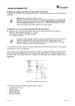
Figure 183:
Thermostat 2
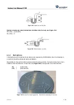
Connection box may reach high temperatures. For suitable connection, use heat-resistant cables
(admissible operation temperature min. 110 °C), for example silicone, Teflon or glass fiber insu-
lated cables.
Cover cap on reset button
Reset button
Содержание ZHK Series
Страница 1: ...ZHK INSTRUCTION MANUAL ...