


Manufacturer
Distributor
5
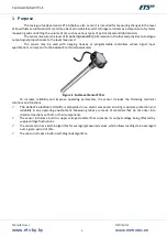
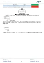
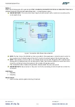
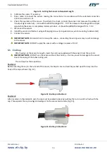
Figure 2. Sensor Components and their Connections
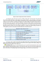
The capacitor is part of the input circuit of an oscillator, which makes the period of the output signal of
the oscillator directly dependent on the capacity of the sensing assembly
–
and, accordingly, on the level of
immersion of the sensing assembly
’s tubes in the fuel. Down the line, a microcontroller measures the period of the
signal put out by the oscillator, normalizes and averages it and verifies whether the measured value is within an
acceptable range. If the result of the verification is affirmative, the microcontroller generates an analogue signal in
the range of its operating voltage (0
…
10 V) which is directly proportional to the level of immersion of the sensing
assembly in the fuel. If the result of the verification is negative or if an error is detected which the built-in self-
diagnosis algorithm recognizes, the microcontroller generates an analogue signal whose voltage represents the
code assigned to the error concerned (see the table
Diagnostic Codes of Sensor Errors
).
Diagnostic Codes of Sensor Errors
Code (Sensor Output Voltage),
V
Error Description
1.0
Sensor’s lower and upper
limits not calibrated
1.2
Sensor’s upper limit not calibrated
1.4
Oscillator frequency equals 0
1.6
Division by zero: the sensor is calibrated to a single point
1.8
EEPROM read error
2.0
Beyond upper limit of range, F>(
Fmax +10%)
2.2
Beyond lower limit of range, F<(
Fmin −10%)
2.4
Calibration terminal shorted
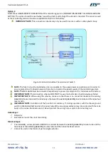
The power supply is designed
to use the input voltage of the
vehicle’s onboard network to generate a
stable supply voltage for the
sensor’s components, to protect the sensor from spikes in the network’s voltage, from
polarity switches in the supply and from other noise.
IMPORTANT NOTE:
Keep in mind that allowing the sensor to operate for extended periods of time under
power supply parameters exceeding, or close to, the rated limit values may result in permanent damage to the
sensor’s protection circuits as a result of ove
rheating or failure of circuit components. In turn, this may render the
sensor non-functional. For operating range values of supply voltage, see the section
Technical Parameters
.
Содержание ETS.A
Страница 1: ...Fuel Level Sensor ETS A Operating Manual...
Страница 9: ...Manufacturer www ets by by Distributor www metrotec ee 9 Legend...
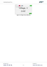
Страница 19: ...Manufacturer www ets by by Distributor www metrotec ee 19 Figure 24 Voltage of Sensor When Dry...
Страница 24: ...Manufacturer www ets by by Distributor www metrotec ee 24...


