


Manufacturer
Distributor
16
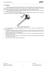
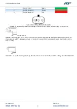
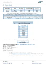
Calibration probe
Calibration signal
3
red
supply power (+)
3
+12 V
1
brown
supply ground (
−
)
2
ground
2
green
output signal
1
Input F/U
6
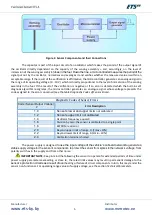
Wire Colour
Pin Designation
Pin Number
Pin Designation
Pin Number
Sensor
DRB-9F
Connector Pin Assignment for Connecting Adapter to Sensor
6.1
Calibration using the Universal Service Adapter (ETS.USA)
Calibration sequence:
1.
Download the file
DUTConfig
from
. Install the application
DUTConfig
.
2.
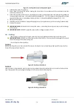
Cut the sensor to required length.
3.
Plug the end cap into the cut ends of the sensing tubes (see section 6.3).
4.
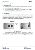
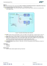
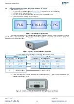
Connect the sensor to PC as shown in Fig. 15.
Figure 15. Connecting the Sensor to PC
To connect the sensor to a PC, use the Universal Service Adapter ETS.USA 2.2 (Fig. 16) available from the
manufacturer. A 3-pin cable (USA
–
ETS.F_A, supplied with the adapter) is required to connect the adapter to the
sensor and to calibrate the sensor.
Figure 16. Universal Service Adapter ETS.USA 2.2
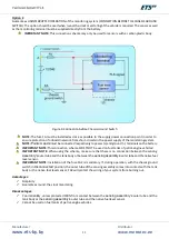
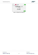
5.
Select operating mode
Voltage measurement
on the adapter (Fig. 17, green LED must blink, see the
adapter’s
operating manual).
Figure 17. Indication of Adapter Operation in
Voltage Measurement
Mode
Содержание ETS.A
Страница 1: ...Fuel Level Sensor ETS A Operating Manual...
Страница 9: ...Manufacturer www ets by by Distributor www metrotec ee 9 Legend...
Страница 19: ...Manufacturer www ets by by Distributor www metrotec ee 19 Figure 24 Voltage of Sensor When Dry...
Страница 24: ...Manufacturer www ets by by Distributor www metrotec ee 24...


