


Option 1
Manufacturer
Distributor
10
Allows the monitoring system to operate
only IF THE CHASSIS GROUND SWITCH IS IN
’CONNECTED’ POSITION
(CONNECTION AFTER THE CHASSIS GROUND SWITCH)
–
a straightforward option.
IMPORTANT NOTE:
This connection scheme may be used for sensors with an aluminium as well as with a
carbon plastic body.
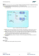
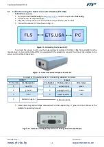
Figure 7. Connection after Chassis Ground Switch
NOTE:
The fuse FA must be installed as close as possible to the supply power connection point in order to
ensure protection of onboard network from short-circuits in the power supply of the monitoring system.
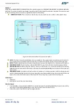
NOTE:
The connection to
А
is made on an onboard power wire (+) with the ignition off. To prevent fuse
blowing due to additional load, it is recommended to place the connection before the native fuse of the
circuit. One of the best connection options is the red wire of the ignition switch.
The connection
to B is made on the vehicle’s chassis under
the instrument panel.
IMPORTANT NOTE:
Ground wires to the sensor and to the monitoring terminal should be run from the
same point.
Advantages:
✓
Reliability
✓
Simplicity
Disadvantages:
✓
Does not allow uninterrupted monitoring of fuel level
Содержание ETS.A
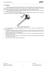
Страница 1: ...Fuel Level Sensor ETS A Operating Manual...
Страница 9: ...Manufacturer www ets by by Distributor www metrotec ee 9 Legend...
Страница 19: ...Manufacturer www ets by by Distributor www metrotec ee 19 Figure 24 Voltage of Sensor When Dry...
Страница 24: ...Manufacturer www ets by by Distributor www metrotec ee 24...


