


Manufacturer
Distributor
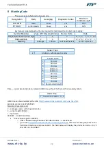
22
8
Marking Code
The sensor is manufactured in two versions.
Designation
Body
Averaging
Diagnostic Codes
Maximum
Cuttable Length
ETS.AОМ
metal
16 sec
yes
50%
ETS.AОУ
carbon plastic
16 sec
yes
50%
Each sensor is diestamped by the interrupted dot method with a 10-digit code marking:
Symbol Meaning
Type of ETS.A Length Code
Device Code
Date
Sequential number of code digit
1
2
3
4 5 6 7 8 9 10
Code example
2
3
L
3 6 3 9 6 4
1
Meaning
Analogue
700 mm
Fuel Level Sensor
14:55 22.03.2013
Sensor Type
2
Analogue, with diagnostic codes
Length Code
1
350 mm
2
500 mm
3
700 mm
4
1000 mm
5
1400 mm
6
265 mm
7
680 mm
8
730 mm
9
750 mm
А
Non-standard length
Date
—
sensor production date, coded in UNIX time without the first and the two last symbols.
UNIX Time
1
Time when marked 0 0
UNIX time can be converted at the URL:
http://www.onlineconversion.com/unix_time.htm
Example. sensor code 22L3639641.
Meaning of example code:
2
–
analogue sensor with diagnostic codes;
2
–
sensor length: 500mm;
L
–
type code;
3639641
–
coded timestamp:
•
code sequence given: 3639641;
o
a
dd
’1’ before first symbol and ’00’ after the last →
1363964100;
o
http://www.onlineconversion.com/unix_time.htm,
enter the resulting sequence in the
field
Unix timestamp
and press
Submit
. The field below will display the production date
–
Fri, 22
Mar 2013 14:55:00 GMT.
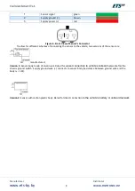
Содержание ETS.A
Страница 1: ...Fuel Level Sensor ETS A Operating Manual...
Страница 9: ...Manufacturer www ets by by Distributor www metrotec ee 9 Legend...
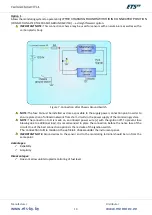
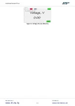
Страница 19: ...Manufacturer www ets by by Distributor www metrotec ee 19 Figure 24 Voltage of Sensor When Dry...
Страница 24: ...Manufacturer www ets by by Distributor www metrotec ee 24...


