


TMCM-1310 TMCL Firmware V1.11 Manual (Rev. 1.16 / 2014-MAR-19)
82
www.trinamic.com
E
XAMPLE
:
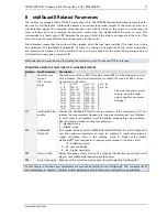
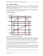
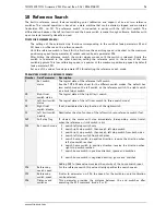
ERROR COMPENSATION
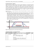
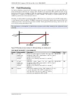
Figure 9.3 Example: online error compensation
In this example the target position has been reached in time though the load on the motor occasionally
got too high. The closed loop error compensation had been able to make up leeway by executing dynamic
error correction parameters. The virtual actual position (grey) calculated by the ramp generator and the
actual position measured by the encoder (blue) merged at the end. Positioning has been carried out
successfully.
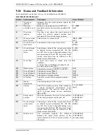
A
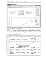
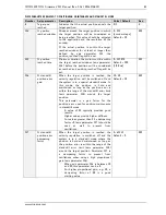
XIS PARAMETERS USED IN POSITIONING MODE
Number Axis parameter
Description
Units / Default
Acc.
0
Target position
The desired position in position mode (see
ramp mode, no. 138).
−2.147.483.648…
+2.147.483.647
[encoder steps]
RW
1
Actual position
The current position of the motor.
−2.147.483.648…
+2.147.483.647
[encoder steps]
RW
2
Target speed
The desired speed in velocity mode (see
ramp mode / parameter 138).
In position mode, this parameter is set by
hardware:
-
during acceleration to maximum speed
-
during deceleration and rest to zero
-327.678.000…
+327.679.999
[pps]
RW
3
Actual speed
The current rotation speed.
-327.678.000…
+327.679.999
[pps]
RW
4
Maximum
positioning
speed
Should not exceed the physically highest
possible value.
0… +327.679.999
[pps]
RWE
5
Maximum
acceleration
The limit for acceleration and deceleration.
1… +24.999.998
[pps/s]
RW


