


TMCM-1310 TMCL Firmware V1.11 Manual (Rev. 1.16 / 2014-MAR-19)
81
www.trinamic.com
9.4
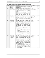
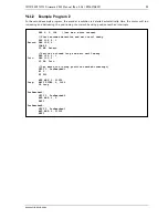
Positioning Mode
In
positioning mode
, a certain target position (SAP 0) is set by the user and the TMCM-1310 uses the ramp
profile parameters for acceleration (SAP 5) and target velocity (SAP 4) to make a ramp movement to the
target position. This is similar to open loop operation. A start/stop velocity can be set (SAP 130) to start
the ramp from a different velocity than zero.
In
closed loop mode
, the actual target position (during movement) and the final target position (as set by
the user) are maintained and the motor does not lose steps or stalls. The dynamic behavior of this
position maintenance can be adapted using various parameters.
O
NLINE
E
RROR
C
OMPENSATION
Target Velocity
Time
V_STARTSTOP
(SAP 130)
0
Max. Positioning
Velocity
(SAP 4)
Max. Correction
Velocity
(SAP 126)
Position
Start Position
Target Position
(SAP 0)
Time
Acceleration
Max.
Acceleration
(SAP 5)
Time
0
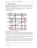
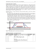
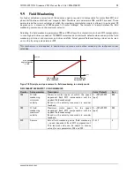
Figure 9.2 Typical Parameters for Positioning Mode
If the
target velocity
and the
actual target position
cannot be reached during movement due to high load
(blue broken line in Figure 9.2), a
maximum correction velocity
(axis parameter 126) can be defined to
compensate the position error between
virtual target position
of the ramp generator (axis parameter 233)
and actual position of the drive (according to encoder feedback /
encoder counter
axis parameter 209).
The behavior of this online error compensation (green broken line in Figure 9.2) can be configured using a
correction velocity proportional factor
(axis parameter 124) and a configurable
maximum following error
(axis parameter 125) that is allowed before actually starting compensation.
If the
maximum correction velocity
is equal to or smaller than the
maximum positioning velocity
, the
target position may not be reached in the time as defined by ramp parameters. Instead, the ramp motion
will be extended until the target position is reached. In case it is desired to reach the target position just
in time as specified by ramp parameters, TRINAMIC recommends setting a higher
maximum
correction
velocity
.
The ramp parameters can be changed on the fly during movement. The ramp will also be updated on-line.


