Q u i c k G u i d e :
Unison AV/Serial Interface v1.0.0 Quick Guide
Unison AV/Serial Interface v1.0.0 Quick Guide
Page 7 of 9
Electronic Theatre Controls, Inc.
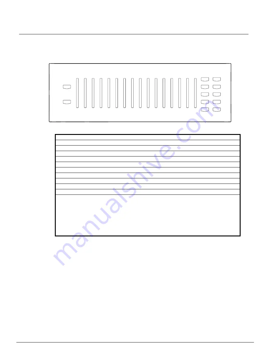
When comparing the button and fader mapping to a physical station, faders are numbered
right to left and buttons 1-10 are on the right side of the faders and 11, 12 are on the left.
The AV/Serial Interface station's buttons and faders are each numbered right to left as 1-
16 respectively.
Binding/Connecting Stations
The AV/Serial Interface and the Unison processor maintain their binding status separately.
(It’s possible to have one bound and the other unbound.) For this guide, “
Connect
” and
“
Disconnect
” refers to the Unison processor’s status (as named in the Unison menus)
and binding refers directly to the station’s status.
You connect/disconnect the AV/Serial Interface station from the Unison processor in the
same manner as any other Unison station. (Arch>Setup>Stations>Connect|Disconnect)
From the AV/Serial Interface station, you type
Escape
. That clears all bindings for the
station.
Station ID Station Description
100
5 buttons
200
10 buttons
800
12 buttons, 4 faders
900
12 buttons, 7 faders
1000
12 buttons, 10 faders
1200
12 buttons, 13 faders
1300
12 buttons, 16 faders (default)
1600
8 switch satellite board
1800
5 buttons, 1 fader
1900
1 key switch, 5 buttons
Notes:
• Changing the station type also processes an Escape command which clears bindings and
takes the station to a disconnected state (it may subsequently rebind with the Unison
Control Module as the wrong station type). This does NOT however disconnect the station
from the Unison Control Module if the station was currently connected (bound at the
processor). Proper operation will only be restored if the station is disconnected and
reconnected as the new station via the Setup Menu of the Unison processor face panel
LCD, and then finally reissuing the station service pin (see Single-byte commands).
Record
Manual
Master
Zone 5
Zone 1
Zone 2
Zone 4
Zone 3
Zone 7
Zone 6
Zone 8
Zone 9
Preset 5
Off
Preset 4
Preset 9
Zone 10
Zone 11
Zone 12
Zone 13
Zone 15
Zone 14
Preset 3
Preset 2
Preset 8
Preset 7
Preset 1
Preset 6
1
2
3
4
6
7
8
9
10
5
11
12
1
2
3
4
5
6
7
8
9
10
11
12
13
14
15
16


