Q u i c k G u i d e :
Unison AV/Serial Interface v1.0.0 Quick Guide
Unison AV/Serial Interface v1.0.0 Quick Guide
Page 3 of 9
Electronic Theatre Controls, Inc.
Light Manager Configuration
• Add a station of the proper type (default is the 12 button, 16 fader station) to the Unison
configuration.
• You should specify the neuron ID in the station's properties just like any other station. (This
is the preferred method of binding stations as it simplifies the process of connecting a
station.)
• Configure the buttons and faders as desired to be used as inputs (causing events in Unison)
or as monitors (watching an LED state to see status of some other event in Unison).
Communication between the station and the serial host
• Use a standard RS232 straight-through cable.
• Station 9 Pin “D style” connector pinout: pin 2 - Transmit data (TX), pin 3 - Receive data
(RX), pin 5 - Common
• Com port settings are: 9600 baud, 8 bits, no parity, 1 stop bit, and Xon/Xoff flow control.
Station Configuration with a Computer Example
• Connect your computer to the station with a serial cable (RS-232)
• Use a communications terminal application such as HyperTerminal to interface with the
station.
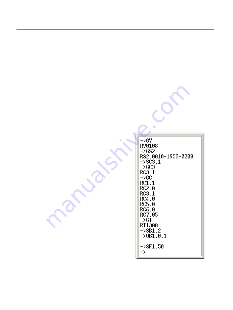
Sample commands: (commands are terminated with carriage return)
• SC 1.1 (Turn on echo mode - You won't see
anything when you type until echo mode is
turned on. Default is off - see
• GV (Get version number - see
• GS2 (Get neuron ID - see
• SC3.1 (Set level and fader scale to 0-100, or
percentages)
• GC3 (Get configuration index 3's value)
• GC (Get all of the configuration values - see
Configuration Settings (nn.cf) on page 6
)
• GT (Get the station type - see
• SB1.2 (Set button 1 - execute a toggle- see
)
• SF1.50 (Set fader 1 to a level of 50- see
and


