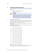
ES5338.1 Carrier Board for Wheel Speed Sensor Simulation - User’s Guide
30
Simulated Sensor Signals
ETAS
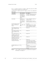
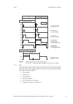
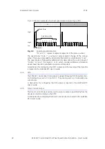
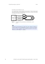
Tab. 3-1 on page 30 and Fig. 3-2 on page 31 explain the actions of the PWM
current pulses of a simulated sensor of type DF11i.
A description for configuring the DF11i signals is located in the LABCAR-RTC
User's Guide.
Tab. 3-1
Action of PWM current pulses of a simulated sensor of type DF11i
(see also Fig. 3-2 on page 31)
Information
Pulse duration
Description
Wheel speed
Dependent of
travel direction
and installation
position of the
sensor
Frequency of PWM signal is pro-
portional to the wheel speed
Tooth voids
Dependent of
travel direction
and installation
position of the
sensor
Tooth void pattern can be cre-
ated by the user.
Output of a current value for
tooth voids defined in the RTIO
Segment change at the
pick-up wheel (pre-bit
phase)
T
0
Adjustable in the
RTIO
Low pulse
followed by high phase whose
length depends on travel direc-
tion and installation position
Travel direction reverse,
regular installation posi-
tion
2 T
0
High pulse
Travel direction forward,
regular installation posi-
tion
4 T
0
High pulse
Travel direction reverse,
installation position error
(field strength too low)
8 T
0
High pulse
Travel direction forward,
installation position error
(field strength too low)
16 T
0
High pulse
Air gap reserve error
(very low field strength)
T
0
High pulse
The air gap reserve indicates
whether the change in magnetic
field strength is below a value
required for error-free function-
ing
Standstill detection or no
field
32 T
0
High pulse
is output in case of a standstill
after a time interval defined in
the RTIO.

