ES5338.1 Carrier Board for Wheel Speed Sensor Simulation - User’s Guide
32
Simulated Sensor Signals
ETAS
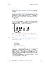
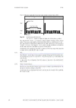
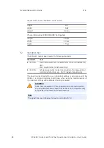
Fig. 3-3 shows an example of a wheel speed sensor signal of type VDA.
Fig. 3-3
Speed pulse and data bits
"N" and "S" represent adjacent segments of the pick-up wheel.
The speed pulse "High 1" is output at every segment change of the pick-up
wheel. This pulse is preceded by an initial bit that sets the current level to "Low".
The speed pulse is followed by additional nine data bits with a current level of
"High 2" or"Low" (for logical 1 or 0), which contain additional information
about travel direction, installation position and standstill.
A description for configuring the DF11i signals and the meaning of the data bits
is located in the LABCAR-RTC User's Guide.
3.3.4
PSI5
The ES5338.1 Carrier Board can generate signals following PSI5 (Peripheral Sen-
sor Interface 5), version V 1.3 and V 2.1. They can be used, e.g. to simulate pres-
sure sensors.
A description for configuring the PSI5 signals is located in the LABCAR-RTC
User's Guide.
3.3.5
Direct Current Output
The Direct Current Output can be used to output a sensor signal directly from the
simulation model running on the RTPC.
A description for configuring the Direct Current output is located in the LABCAR-
RTC User's Guide.
Low
High 2
High 1
0
2
3
1
4
5
6
7
8
Data Protocol Bits
Speed Pulse
Initial Bit
N
S

