background image

Chapter 4 Operation

- 38 -

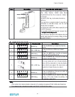
Step

Step

Step

Step

Item

Item

Item

Item

Description

Description

Description

Description

Reference

Reference

Reference

Reference

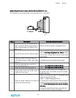
1

Installation

Install the servomotor and servodrive according to the installation conditions.

(Do not connect the servomotor to the machine because the servomotor will

be operated first under the no-load condition for checking.)

-

2

Wiring

Connect the power supply circuit (L1, L2 and L3), servomotor wiring (U, V,

W), I/O signal wiring (CN1), and encoder wiring (CN2). But during

(1)

(1)

(1)

(1) Trial

Trial

Trial

Trial

Operation

Operation

Operation

Operation for

for

for

for Servomotor

Servomotor

Servomotor

Servomotor Without

Without

Without

Without Load

Load

Load

Load

, disconnect the CN1 connector.

-

3

Turn the power

ON

Turn the power ON. Using the panel operator to make sure that the

servodrive is running normally. If using a servomotor equipped with an

absolute encoder, please perform the setup for the absolute encoder.

-

4

Execute JOG

operation

Execute JOG operation with the servomotor alone under the no-load

condition.

JOG

Operation

5

Connect

input

signals

Connect the input signals (CN1) necessary for trial operation to the

servodrive.

-

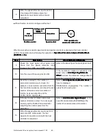
6

Check input

signals

Use the internal monitor function to check the input signals.

Turn the power ON, and check the emergency stop, brake, overtravel, and

other protective functions for correct operation.

-

7

Input the

Servo-ON

signal

Input the Servo-ON signal, and turn ON the servomotor.

Host

Reference

8

Input reference

Input the reference necessary for control mode, and check the servomotor

for correct operation.

Host

Reference

9

Protective

operation

Turn the power OFF, and connect the servomotor to the machine.

If using a servomotor equipped with an absolute encoder, set up the

absolute encoder and make the initial settings for the host controller to

match the machine’s zero position.

-

Содержание EMG-20ADA22

Страница 1: ...servo system system system system User s Manual V 1 08 Estun Limited Warranty This manual does not entitle you to any rights Estun reserves the right to change this manual without prior notice All rig...

Страница 2: ...s Procedures for wiring the servodrives and servomotors Procedures for operation of the servodrives Procedures for using the panel operator Communication protocols Ratings and characteristics Intended...

Страница 3: ...vibration and shock Perform noise reduction and grounding properly Please comply with the following instructions strictly to avoid the noisy generated by signal lines 1 Separate high voltage cables f...

Страница 4: ...n Orientation 16 2 1 5 Handling Oil and Water 16 2 1 6 Cable Tension 17 2 2 Servodrive 17 2 2 1 Storage 17 2 2 2 Installation Sites 17 2 2 3 Installation Orientation 18 2 2 4 Installation Method 18 Ch...

Страница 5: ...rol Mode Selection 48 4 3 Setting Common Basic Functions 49 4 3 1 Setting the Servo ON Signal 49 4 3 2 Switching the Servomotor Rotation Direction 50 4 3 3 Setting the Overtravel Limit Function 51 4 3...

Страница 6: ...RDY Output 92 Chapter 5 93 Panel Operator 93 5 1 Basic Operation 93 5 1 1 Functions on Panel Operator 93 5 1 2 Resetting Servo Alarms 93 5 1 3 Basic Mode Selection 94 5 1 4 Status Display Mode 94 5 1...

Страница 7: ...sal 118 6 3 3 Data Communication Address of Servo State 119 Chapter 7 121 Specifications and Characters 121 7 1 Servodrive Specifications and Models 121 7 2 Servodrive Dimensional Drawings 123 Appendi...

Страница 8: ...ck Check Check Items Items Items Items Comments Comments Comments Comments Are the delivered products the ones that were ordered Check the model numbers marked on the nameplate on the servomotor and s...

Страница 9: ...no brake in EMG ADA servomotor ESTUN Servomotor 1 2 3 4 5 6 7 EMG Model 1 2 Rated Output 4 Encoder 7 Option Code Rated Output Code Encoder Code Option 10 1 0kW D Incremental encoder 131072P R 1 None...

Страница 10: ...3 L3 L3 L 1C L 1C L 1C L 1C L 2C L 2C L 2C L 2C 1 1 1 1 2 2 2 2 B1 B1 B1 B1 B2 B2 B2 B2 B3 B3 B3 B3 U V W CH ARG E CH ARG E CH ARG E CH ARG E L1 L2 L3 CN3 CN3 CN3 CN3 CN4 CN4 CN4 CN4 CN1 CN1 CN1 CN1 C...

Страница 11: ...ser s manual V 1 08 10 ProNet 7 5 11 15KW Nameplate Nameplate Nameplate Nameplate CN3 CN3 CN3 CN3 CN4 CN4 CN4 CN4 CN1 CN1 CN1 CN1 CN2 CN2 CN2 CN2 Servodrive model Applicable power supply Applicable se...

Страница 12: ...10 1 0 kW 15 1 5 kW 20 2 0 kW 30 3 0 kW 50 5 0 kW 75 7 5 kW 1A 11 kW 1E 15 kW Voltage Voltage Voltage Voltage A 200VAC D 400VAC Control Control Control Control M M M Mode ode ode ode M Speed control t...

Страница 13: ...2 L2 L3 L3 L3 L3 L1 C L1 C L1 C L1 C L2 C L2 C L2 C L2 C 1 1 1 1 2 2 2 2 B1 B1 B1 B1 B2 B2 B2 B2 B3 B3 B3 B3 U V W CHARGE CHARGE CHARGE CHARGE Power on indicator Power on indicator Power on indicator...

Страница 14: ...terminals Connects to the servomotor power line L1 L2 L3 CN3 CN3 CN3 CN3 CN4 CN4 CN4 CN4 CN1 CN1 CN1 CN1 CN2 CN2 CN2 CN2 L1C L1C L1C L1C L2C L2C L2C L2C B1 B2 B3 U V W 1 2 CHARGE POWER Charge indicato...

Страница 15: ...evices I I I I O signal connector O signal connector O signal connector O signal connector Used for reference input signals and sequence I O signals Encoder connector Encoder connector Encoder connect...

Страница 16: ...otor is designed for indoor use Install the servomotor in an environment which meets the following conditions Free from corrosive and explosive gases Well ventilated and free from dust and moisture Am...

Страница 17: ...horiz ontally or vertically 2 1 5 Handling Oil and Water If the servomotor is used in a location that is subject to water or oil drops make sure of the servomotor protective specification If the servo...

Страница 18: ...tallation installation installation When installed in a control panel Design the control panel siz e unit layout and cooling method so that the temperature around the periphery of the servodrive does...

Страница 19: ...must be oriented this way because it is designed to be cooled by natural convection or a cooling fan if required Firmly secure the servodrive through two mounting holes 2 2 4 Installation Method When...

Страница 20: ...side side by by by by side side side side When installing servodrives side by side provide at least 10 mm space between them and at least 50 mm space above and below them as shown in the figure above...

Страница 21: ...L1 L2 L3 Main circuit power supply input terminal 200 A Three phase 200 230VAC 10 15 50 60Hz 400 D Three phase 380 440VAC 10 15 50 60Hz U V W Servomotor connection terminals Connects to the servomotor...

Страница 22: ...ase Circuit Breaker Surge Protector Surge Protector Surge Protector Surge Protector Noise Filter Be sure to connect a surge suppressor to the excitation coil of the magnetic contactor and relay Noise...

Страница 23: ...L1C CN2 1Ry 1D 24V 0V 1Ry 1PL Servo Alarm Display ALM 7 ALM 8 ProNet ProNet ProNet ProNet Series Servodrive 1 2 B1 B2 External Regenerative Resistor Ground Terminal Encoder Servodrive Magnetic Contac...

Страница 24: ...6LS32A Manufactured by TI or the Equivalent Signal Allocations can be Modified V CMP Speed Coincidence COIN Positioning Completion TGON Rotation Detection S RDY Servo Ready CLT Torque Limit Detection...

Страница 25: ...ith reference pulse Stops reference pulse input when ON P OT N OT 16 17 Forward run prohibited Reverse run prohibited Overtravel prohibited Stops servomotor when ON PCL NCL 41 42 Function selected by...

Страница 26: ...nal PBO 23 PCO 24 Phase C signal Zero point pulse Phase C signal PCO 25 FG Shell Connected to frame ground if the shield wire of the I O signal cable is connected to the connector shell Speed Speed Sp...

Страница 27: ...7 T REF 3 AGND AGND 28 AGND AGND 4 Reserved 29 Reserved 5 TGON Running signal output 30 PULS Reference pulse input 6 TGON 31 PULS 7 ALM Servo alarm 32 SIGN Reference sign input 8 ALM 33 SIGN 9 S RDY S...

Страница 28: ...output output output output circuit circuit circuit circuit The amount of two phase phase A and phase B pulse output signals PAO PAO PBO PBO and zero point pulse signals PCO PCO are output via line dr...

Страница 29: ...the equivalent or the equivalent P B O P B O 2 2 2 3 P Ph as e B P C O P C O 2 4 2 5 P Ph as e C 0V D G N D 0V 5 0 Shell Shell Shell Shell N ote There are no BAT and B A T signals in incremental enco...

Страница 30: ...tery For an absolute encoder 8 PS PG serial signal input 18 BAT Battery For an absolute encoder 9 PG5V PG power supply 5V 19 GND PG power supply 0V Terminal Terminal Terminal Terminal No No No No Name...

Страница 31: ...tion 1 5V Power supply 5V DC 2 5V 3 485 RS 485 communication terminal 4 DGND Ground 5 DGND 6 485 RS 485 communication terminal 7 CANH CAN communication terminal 8 CANL CAN communication terminal Termi...

Страница 32: ...Surge Protector Magnetic Contactor Molded case Circuit Breaker 1Ry 1PL Servo Alarm Display 1 5V 2 485 3 DGND 4 DGND 5 485 6 CANH 7 CANL 8 N C 1 N C 2 485 3 DGND 4 DGND 5 485 6 CANH 7 CANL 8 PAO 20 PAO...

Страница 33: ...0V Surge Protector Magnetic Contactor Molded case Circuit Breaker 1Ry 1PL Servo Alarm Display 1 5V 2 485 3 DGND 4 DGND 5 485 6 CANH 7 CANL 8 N C 1 N C 2 485 3 DGND 4 DGND 5 485 6 CANH 7 CANL 8 PAO 20...

Страница 34: ...Magnetic Contactor Molded case Circuit Breaker 1Ry 1PL Servo Alarm Display 1 5V 2 485 3 DGND 4 DGND 5 485 6 CANH 7 CANL 8 N C 1 N C 2 485 3 DGND 4 DGND 5 485 6 CANH 7 CANL 8 PAO 20 PAO 21 PBO 22 PBO 2...

Страница 35: ...Rated Torque Open collectorReference Use Position Reference Signal allocatons can be modified S ON Servo ON P CON P Control P OT Forward Run Prohibited N OT Reverse Run Prohibited ALM RST Alarm Reset...

Страница 36: ...ed pairWires Shell Connect Shield to ConnectorShell Signal allocatons can be modified S ON Servo ON P CON P Control P OT Forward Run Prohibited N OT Reverse Run Prohibited ALM RST Alarm Reset CLR Clea...

Страница 37: ...Signal allocatons can be modified S ON Servo ON P CON P Control P OT Forward Run Prohibited N OT Reverse Run Prohibited ALM RST AlarmReset CLR Clear Error Pulse P CL Forward Torque Limit N CL Reverse...

Страница 38: ...he Secure the servomotor flange to the m achine m achine m achine m achine but do not connect the but do not connect the but do not connect the but do not connect the servomotor shaft to the load shaf...

Страница 39: ...s running normally If using a servomotor equipped with an absolute encoder please perform the setup for the absolute encoder 4 Execute JOG operation Execute JOG operation with the servomotor alone und...

Страница 40: ...the coupling between the servomotor and the machine and secure only the servomotor without a load To prevent accidents initially perform the trial operation for servomotor under no load conditions wit...

Страница 41: ...er wiring is incorrect If an alarm is displayed turn OFF the power find the problem and correct it 4 Release the brake before driving the servomotor when a servomotor with brake is used When using a s...

Страница 42: ...JOG speed is 500 min 1 Step Step Step Step Display Display Display Display after after after after operation operation operation operation Panel Panel Panel Panel operator operator operator operator...

Страница 43: ...Range Range Range Setting Setting Setting Setting Unit Unit Unit Unit Factory Factory Factory Factory Setting Setting Setting Setting Setting Setting Setting Setting Validation Validation Validation V...

Страница 44: ...ference input to the servodrive Un001 min 1 Refer to 5 1 6 5 1 6 5 1 6 5 1 6 Operation Operation Operation Operation in in in in Monitor Monitor Monitor Monitor Mode Mode Mode Mode 5 Check the Un000 m...

Страница 45: ...actual number of rotation by visual inspection and the Un004 rotation angle pulse Refer to 5 1 6 5 1 6 5 1 6 5 1 6 Operation Operation Operation Operation in in in in Monitor Monitor Monitor Monitor...

Страница 46: ...ervomotor rotation direction is the same as the reference Check the input pulse polarity and input reference pulse form 8 Input the pulse reference with the large number of servomotor rotation from th...

Страница 47: ...ned OFF 4 Check that the servodrive is servo OFF status and then turn ON the power to the machine host controller Check again that the protective function in step 1 operates normally Refer to 4 3 4 3...

Страница 48: ...Review Items Items Items Items JOG Operation Constan speed reference input from host controller Servomotor speed Check servomotor speed as follows Use the servomotor speed monitor Un000 on the panel...

Страница 49: ...ference reference reference reference Controls the position of the servomotor using pulse train position reference Controls the position with the number of input pulses and controls the speed with the...

Страница 50: ...nector Connector Connector Pin Pin Pin Pin Number Number Number Number Setting Setting Setting Setting Meaning Meaning Meaning Meaning Input S ON CN1 14 Factory setting ON low level Servomotor power O...

Страница 51: ...drive CN1 connector correctly Parameter Parameter Parameter Parameter Name Name Name Name Reference Reference Reference Reference Forward Forward Forward Forward reference reference reference referenc...

Страница 52: ...reverse rotation is possible during forward overtravel Servomotor forward rotation direction Servomotor forward rotation direction Servomotor forward rotation direction Servomotor forward rotation dir...

Страница 53: ...againg to enable the new settings A parameter can be used to re allocate input connector number for the P OT and N OT signals Refer to 3 2 2 3 2 2 3 2 2 3 2 2 I O I O I O I O Signal Signal Signal Sign...

Страница 54: ...rt circuiting by a circuit of servodrive Coast to a stop Stops naturally with no brake by using the friction resistance of the servomotor in operation Plug braking Stops by using plug braking limit to...

Страница 55: ...ference to 0V when the brake is applied 3 When forming a position loop do not use a mechanical brake while the servomotor is stopped because the servomotor enters servolock status 1 1 1 1 Wiring Wirin...

Страница 56: ...put signals other than BK signal refer to 3 2 2 3 2 2 3 2 2 3 2 2 I O I O I O I O Signal Signal Signal Signal Names Names Names Names and and and and Functions Functions Functions Functions Pn506 Pn50...

Страница 57: ...Setting Setting Setting Setting Range Range Range Range Setting Setting Setting Setting Unit Unit Unit Unit Factory Factory Factory Factory Setting Setting Setting Setting Setting Setting Setting Set...

Страница 58: ...rn Multiturn MultiturnData Data Data Data Action Action Action Action when when when when limit limit limit limit is is is is exceeded exceeded exceeded exceeded ProNet Series 16 bit multiturn 17 bit...

Страница 59: ...ed OFF the data must be backedup by a battery Please purchase the specialcable and battery case mabe by Estun if an absolute encoder is used 1 Install the battary to the servodrive A Open the shell of...

Страница 60: ...he multiturn data is lost Please reset the absolute encoder after changing the battery 4 4 4 Absolute Encoder Setup Fn010 Fn011 Setting Setting Setting Setting up up up up the the the the absolute abs...

Страница 61: ...etting Setting Setting Setting Setting Setting Setting Validation Validation Validation Validation 0 3000 rpm v 150 Immediately Sets the analog voltage level for the speed reference V REF necessary to...

Страница 62: ...Number Number Number Name Name Name Name Input V Ref CN1 1 Speed Reference Input V Ref CN1 2 Speed Reference Input AGND CN1 3 Signal Ground for Speed Reference Input The above inputs are used for spee...

Страница 63: ...unction Function Function Function Note Note Note Note The speed reference offset must be automatically adjusted with the servo OFF Adjust the speed reference offset automatically in the following pro...

Страница 64: ...Chapter 4 Operation 63 7 Press ENTER key to return to the Fn003 display of the utility function mode 8 Thus the speed reference offset automatic adjustment is completed...

Страница 65: ...ey to select the utility function mode 2 Press the INC or DEC key to select parameter Fn004 3 Press the ENTER key to enter into the speed reference offset manual adjustment mode 4 Turn ON the servo ON...

Страница 66: ...these parameters as follows Pn306 The time interval from the time the servomotor starts until the servomotor maximum speed is reached Pn307 The time interval from the time the servomotor is operating...

Страница 67: ...Speed Reference Speed Reference V V V V R E F R E F R E F R E F Zero Clamp Zero Clamp Zero Clamp Zero Clamp P P P P C O N C O N C O N C O N When the When the When the When the P P P P CON signal is tu...

Страница 68: ...speed of the servomotor the maximum speed will be used Type Type Type Type Signal Signal Signal Signal Name Name Name Name Connector Connector Connector Connector Pin Pin Pin Pin Number Number Number...

Страница 69: ...uency Frequency Frequency dividing dividing dividing dividing circuit circuit circuit circuit C N C N C N C N 1 1 1 1 Phase A Phase A Phase A Phase A P A O P A O P A O P A O Phase B Phase B Phase B Ph...

Страница 70: ...output per revolution P A O P A O P A O P A O P B O P B O P B O P B O 1 1 1 1 revolution revolution revolution revolution Preset value Preset value Preset value Preset value 1 6 1 6 1 6 1 6 Type Type...

Страница 71: ...SIGN CN1 32 Reference sign input SIGN CN1 33 Reference sign input Parameter Parameter Parameter Parameter Reference Reference Reference Reference Pulse Pulse Pulse Pulse Form Form Form Form Input Inpu...

Страница 72: ...and and and SIGN SIGN SIGN SIGN reference reference reference reference Pn004 0 Does not inverse PULS reference and SIGN reference 1 Does not inverse PULS reference Inverses SIGN reference 2 Inverses...

Страница 73: ...iven as n m where m is the rotation of the servomotor and n is the rotation of the load shaft Electronic gear ratio 202 201 Pn Pn A B n m units reference revolution shaft load per ce dis Travel pulses...

Страница 74: ...Configuration Configuration Configuration Configuration Ball Ball Ball Ball Screw Screw Screw Screw Disc Disc Disc Disc Table Table Table Table Belt Belt Belt Belt and and and and Pulley Pulley Pulley...

Страница 75: ...autions for open collector output When the open collector output is used input signal noise margin lowers When a position error caused by the noise occurs change the parameter as follows Parameter Par...

Страница 76: ...ignal Maximum reference frequency 500kpps For open collector output 200kpps t1 t2 0 1 s t3 t7 0 1 s t4 t5 t6 3 s 1 0 s T 100 5 0 S IG N PU LS t1 t2 t3 t4 T Forwardreference Reverse reference t5 t6 t7...

Страница 77: ...urrent i will be within 7 to 15 mA Host controller Line driver Servodrive Photocoupler PU LS PU LS 3 0 3 1 150 C N 1 S IG N S IG N 3 2 3 3 150 Represents twisted pair wires Host controller Servodrive...

Страница 78: ...diagram for position control is shown as below Differential Feed forward B A Feed forward filter time constant Offs et Positioning complete Current loop Speed loop K P Error counter Smoothing 1 2 4 di...

Страница 79: ...ation Time Constant Setting Setting Setting Setting Range Range Range Range Setting Setting Setting Setting Unit Unit Unit Unit Factory Factory Factory Factory Setting Setting Setting Setting Setting...

Страница 80: ...ion suppression function is disabled or can not reach the expected effect in the following condition Vibration is pricked up due to external force Vibration frequency is out of 5 0Hz to 50 0Hz The mec...

Страница 81: ...ting Setting Validation Validation Validation Validation 50 500 0 1Hz 100 Immediately Pn412 Low Low Low Low frequency frequency frequency frequency vibration vibration vibration vibration damp damp da...

Страница 82: ...Setting Setting Setting Setting Setting Setting Setting Setting Validation Validation Validation Validation 0 5000 1Puls 10 Immediately The positioning completion COIN signal is output when the differ...

Страница 83: ...t t1 1 1 1 t t t t2 2 2 2 t t t t1 1 1 1 t t t t2 2 2 2 0000 5 5 5 5m s m s m s m s P P P P C O N C O N C O N C O N Reference pulse Reference pulse Reference pulse Reference pulse Input reference pul...

Страница 84: ...tion Validation Validation Validation 10 100 0 1V 100 33 Immediately This sets the analog voltage level for the torque reference T REF that is necessary to operate the servomotor at the rated torque E...

Страница 85: ...oltage reference Pn005 1 2 6 8 9 The torque reference input gain is set in Pn400 For setting details refer to 4 7 1 4 7 1 4 7 1 4 7 1 Setting Setting Setting Setting Parameters Parameters Parameters P...

Страница 86: ...erence offset manual adjustment Fn004 Note Note Note Note The analog reference offset must be automatically adjusted with the servo OFF 2 Manual 2 Manual 2 Manual 2 Manual Adjustment Adjustment Adjust...

Страница 87: ...t Safe operation with speed limit Safe operation with speed limit Safe operation with speed limit Safe operation with speed limit Speed lim it Speed lim it Speed lim it Speed lim it Parameter Paramet...

Страница 88: ...Range Range Range Range Setting Setting Setting Setting Unit Unit Unit Unit Factory Factory Factory Factory Setting Setting Setting Setting Setting Setting Setting Setting Validation Validation Valida...

Страница 89: ...internally set speed Input Input Input Input Signal Signal Signal Signal Servomotor Servomotor Servomotor Servomotor Rotation Rotation Rotation Rotation Direction Direction Direction Direction Speed S...

Страница 90: ...P E E D SP E E D SP E E D2 2 2 2 SP E E D SP E E D SP E E D SP E E D3 3 3 3 Acceleration Acceleration Acceleration Acceleration deceleration are done for the deceleration are done for the deceleration...

Страница 91: ...Factory Factory Factory Seeting Seeting Seeting Seeting Setting Setting Setting Setting Validation Validation Validation Validation 0 300 1 300 Immediately The settings in these parameters are constan...

Страница 92: ...tting Setting Setting Setting Range Range Range Range Setting Setting Setting Setting Unit Unit Unit Unit Factory Factory Factory Factory Setting Setting Setting Setting Setting Setting Setting Settin...

Страница 93: ...torque lim it reverse rotation torque lim it reverse rotation torque lim it Torque reference Torque reference Torque reference Torque reference P n P n P n P n 401 401 401 401 forward rotation torque...

Страница 94: ...5 Speed control contact reference Position control pulse train reference H 6 Speed control contact reference Torque control analog voltage reference H 7 Position control pulse train reference Speed co...

Страница 95: ...ange Setting Setting Setting Setting unit unit unit unit Factory Factory Factory Factory setting setting setting setting Setting Setting Setting Setting validation validation validation validation 0 3...

Страница 96: ...RST input signal There is no need to clear the servo alarms if it turns the main circuit power supply OFF Note Note Note Note After an alarm occurs remove the cause of the alarm before resetting it Ke...

Страница 97: ...ected in the following order Power ON Status display mode Parameter setting mode Monitor mode Utility function mode 5 1 4 Status Display Mode The status display mode displays the servodrive status as...

Страница 98: ...Speed reference input Lit if input speed reference exceeds preset value Not lit if input speed reference is below preset value Preset value Pn503 factory setting is 20 min 1 Reference pulse input Lit...

Страница 99: ...lect the parameter setting mode 2 Press INC key or DEC key to select parameter number 3 Press ENTER key to display the current data of Pn102 4 Press the INC or DEC key to change the data to the desire...

Страница 100: ...Modes Modes Modes Modes Contents of Monitor Mode Display Monitor Monitor Monitor Monitor Number Number Number Number Monitor Monitor Monitor Monitor Display Display Display Display Internal status bit...

Страница 101: ...CN1 40 6 PCL CN1 41 7 NCL CN1 42 Monitor Monitor Monitor Monitor Number Number Number Number Display Display Display Display LED LED LED LED Number Number Number Number Content Content Content Conten...

Страница 102: ...ber Alarm Code 4 Press the INC or DEC key to display other alarms occurred in recent 5 Press the ENTER key the display will return to Fn000 Note Note Note Note Hold the ENTER key for one second with a...

Страница 103: ...the INC or DEC key to select the function number of parameter settings initialization 3 Press the ENTER key to enter into parameter settings mode 4 Hold the ENTER key for one second the parameters wi...

Страница 104: ...s the ENTER key to enter into JOG operation mode 4 Press the MODE key to enter into servo ON servomotor power ON status 5 Press the MODE key to switch between the servo ON and servo OFF status The ser...

Страница 105: ...ence offset manual adjustment for a position loop The zero clamp speed control function can be used to force the servomotor to stop while the zero speed reference is given Note Note Note Note The spee...

Страница 106: ...mode of the speed torque reference offset This mode operates in the same way as the automatic adjustment mode except that the amount of offset is directly input during the adjustment The offset adjus...

Страница 107: ...TER key to enter into the speed reference offset manual adjustment mode 4 Turn ON the servo ON signal the display is shown as follows 5 Hold the ENTER key for one second the speed reference offset wil...

Страница 108: ...ion signal automatically in the following procedure 1 Press the MODE key to select the utility function mode 2 Press the INC or DEC key to select the utility function number Fn005 3 Press the ENTER ke...

Страница 109: ...n number Fn006 3 Press the ENTER key to enter into the manual adjustment of the servomotor current detection signal mode 4 Press the MODE key to switch between the phase U o _ CuA and phase V 1_ Cub s...

Страница 110: ...turn to the utility function mode display Fn007 5 2 8 Position Teaching Function Perform the position teaching function in the following procedure 1 Press the MODE key to select the utility function m...

Страница 111: ...der multiturn data and alarm reset is completed 5 2 11Absolute Encoder RelatedAlarms Reset 1 Press the MODE key to select the utility function mode 2 Press the INC or DEC key to select the utility fun...

Страница 112: ...of servodrive is always used as communication cable input terminal and CN4 is always used as communication cable output terminal If still need to connect slave stations the communication cable is con...

Страница 113: ...700 0 Pn700 0 Pn700 0 MODBUS MODBUS MODBUS MODBUS baud baud baud baud rate rate rate rate 0 4800bps 1 9600bps 2 19200bps Pn700 1 Pn700 1 Pn700 1 Pn700 1 Communication Communication Communication Commu...

Страница 114: ...CII code for number 0 to 9 character A to F are as follows RTU RTU RTU RTU Mode Mode Mode Mode Every 8 bit data is consisted by two 4 bit hexadecimal data that is to say a normal hexadecimal data For...

Страница 115: ...CII codes DATA n 1 Data content n word 2n byte contain 4n ASCII codes n 12 DATA 0 LRC Checking code 1 byte contains two ASCII codes End 1 End code 1 0DH CR End 0 End code 0 0A H LF Start bit 0 1 2 3 4...

Страница 116: ...TX communication communication communication communication start start start start ASCII mode character STX Sleep interval of at least 4 bytes transmission time ADR Communication address 1 byte CMD Re...

Страница 117: ...nce reference reference and and and and DATA DATA DATA DATA data data data data Data structure is determined by command code Regular command code is shown as follows Command code 03H read N words word...

Страница 118: ...0 6 4 LRC checking 9 3 End 1 0DH CR End 0 0AH LF ADR 01 H CMD 03 H Data start address 02 H high bit 00 H low bit Data number count as word 00 H 02 H CRC checking C5 H low bit CRC checking B3 H high b...

Страница 119: ...s F8H when 2 is used to compensate 08H so LRC is F 8 CRC CRC CRC CRC calculation calculation calculation calculation of of of of RTU RTU RTU RTU mode mode mode mode RTU mode uses CRC Cyclical Redundan...

Страница 120: ...nd1 End0 End0 End0 End0 Communication Communication Communication Communication is is is is complete complete complete complete ASCII ASCII ASCII ASCII mode mode mode mode Communication is end with 0D...

Страница 121: ...Pn100 is 0 6 The servodrive will feedback an error frame the error code is 03H Beyond the parameter s maximum value or minimum value Host Host Host Host controller controller controller controller dat...

Страница 122: ...resent location Unit 10000 reference pulses Read only 0811 Error pulse counter low 16 bits Read only 0812 Error pulse counter high 16 bits Read only 0813 Setting pulse counter low bits Unit 1 referenc...

Страница 123: ...ommunication address 0807H speed setting is FB16H Therefore the speed setting is 1258r m 4 MODBUS communication IO signal Use communication to control digital IO signal This data will not be saved aft...

Страница 124: ...10 15 50 60Hz Three phase 380 440VAC 10 15 50 60Hz Contro Circuit Single phase 200 230VAC 10 15 50 60Hz Single phase 380 440VAC 10 15 50 60Hz Pow er Supply Capacity kVA 0 5 0 9 1 3 1 8 2 5 3 5 4 5 7...

Страница 125: ...pulses any Sequenc e Input Number of channels 8 channels Function Signal allocations and positive negative logic modifications Servo ON S ON P control P CON alarm reset ALM RST position error clear C...

Страница 126: ...et 02A 04A ProNet 02A 04A Three phase Three phase Three phase Three phase 200V 200V 200V 200V ProNet 08A 10A ProNet 08A 10A ProNet 08A 10A ProNet 08A 10A Nameplate Unit mm Unit mm Cooling Fan Extended...

Страница 127: ...n u t e s b e f o r e s e r v i c i n g W ARNI N G W ARNI N G W ARNI N G W ARNI N G M ay cause el e ct r i c shock C A U T I O N C A U T I O N C A U T I O N C A U T I O N Approx mass 5 0kg Unit mm CN1...

Страница 128: ...le M o u n tin g Ho le Dia g ra m Co o lin g Fa n G r o u n d Te r m in a l 2 M6 Scr e w Exte n d e d M o d u le Co o lin g Fa n Na m e p la te Air Flo w U s e p r o p e r g r o u n d i n g t e c h n...

Страница 129: ...ss 0 1111 0 After restart Pn001 Binary Binary Binary Binary Pn001 0 CCW CW selection Pn001 1 Analog speed limit enabled Pn001 2 Analog torque limit enabled Pn001 3 2nd electronic gear enabled 0 1111 0...

Страница 130: ...l analog reference speed control analog reference A Speed control analog reference zero clamp B Position control pulse train position control inhibit C Position control contact reference D Speed contr...

Страница 131: ...peed setting 3 Value of speed setting 4 Fixed PI 0 4 0 After restart Pn117 Torque switching threshold 0 300 200 Immediately Pn118 Offset counter switching threshold reference pulse 0 10000 0 Immediate...

Страница 132: ...d rpm 0 6000 500 Immediately Pn306 Soft start acceleration time ms 0 10000 0 Immediately Pn307 Soft start deceleration time ms 0 10000 0 Immediately Pn308 Speed filter time constant ms 0 10000 0 Immed...

Страница 133: ...r restart Pn512 Bus control input node low bit enable 0 1111 0 Immediately Pn513 Bus control input node low bit enable 0 1111 0 Immediately Pn514 Input port filter 0 2ms 0 1000 1 Immediately Pn515 Res...

Страница 134: ...on protocol selection Pn700 3 Reserved 0 0x0182 0x0151 After restart Pn701 MODBUS axis address 1 247 1 After restart Pn840 Hex Hex Hex Hex Pn840 0 Encoder model selection Pn840 1 Reserved Pn840 2 Rese...

Страница 135: ...hibited prohibited prohibited prohibited N OT N OT N OT N OT 0 External N OT enabled Operate in the time sequence setting in Pn004 0 when travel limit occurs 1 External N OT disabled Pn000 3 Pn000 3 P...

Страница 136: ...Referencepulse P n 201 Electronicgearnumerator 1 P n 203 Electronicgearnumerator 2 P n 201 Electronicgearnumerator 1 t1 t2 1m s 1 Corresponding time sequence t1 t2 PCON disabled PCON enabled PCON dis...

Страница 137: ...ad enhancement function 1 With overload enhancement function which can enhance the overload capacity when servomotor exceeds the 2 times rated overload It is used in frequent power ON OFF occasions Pn...

Страница 138: ...ON P P P P control control control control 1 Position control pulse train reference PCON PCON PCON PCON OFF OFF OFF OFF PI PI PI PI control control control control ON ON ON ON P P P P control control...

Страница 139: ...ference reference reference 9 Torque control analog reference speed control analog reference PCON PCON PCON PCON OFF OFF OFF OFF Torque Torque Torque Torque control analog control analog control analo...

Страница 140: ...bled Pn006 3 Pn006 3 Pn006 3 Pn006 3 Reference Reference Reference Reference input input input input filter filter filter filter for for for for open open open open collector collector collector colle...

Страница 141: ...eliminate or lighten mechanical vibration But incorrect setting will result to mechanical vibration Unit 0 1ms Pn106 Load inertia percentage Immediately P S Setting value load inertia rotor inertia 1...

Страница 142: ...switching condition After restart P S 0 Torque reference percentage 1 Value of offset counter 2 Value of acceleration speed setting 3 Value of speed setting 4 Fixed PI Pn117 Torque switching threshol...

Страница 143: ...too large Pn130 Friction Load Immediately P S Frictin load or fixed load compensation Pn131 Friction compensation speed hysteresis area Immediately P S Threshold of friction compensation start Pn132...

Страница 144: ...ternal speed 2 Immediately S Pn303 Internal speed 3 Immediately S Pn304 Parameter speed Immediately S The parameter can be set to positive or negative When control mode is set to D it determines the s...

Страница 145: ...ately P S T Servomotor output torque limit value Pn406 Speed limit during torque control Immediately T Servomotor output torque limit value during torque control Pn407 Notch filter 1 frequency Immedia...

Страница 146: ...parameter setting time Basic Basic Basic Basic waiting waiting waiting waiting flow flow flow flow Standard setting BK output braking action and servo OFF are at the same time Now the machine movable...

Страница 147: ...CN1_09 CN1_10 Corresponding signal of each data is shown as follows 0 COIN VCMP 1 TGON 2 S RDY 3 CLT 4 BK Pn512 Bus control input node low bit enabled Immediately P S T Bus communication input port en...

Страница 148: ...point control Immediately P The two parameters are used in combination and the algebraic sum of them is the position of JPOS0 needs to reach The number of servomotor rotation revolutions is related w...

Страница 149: ...start signal canceling start signal can immediately stop inside pulse Return to programme start point process step when reset 3 PCON change step need start signal canceling start signal can immediate...

Страница 150: ...2 MODBUS ASCII 1 7 E 1 MODBUS ASCII 2 7 O 1 MODBUS ASCII 3 8 N 2 MODBUS ASCII 4 8 E 1 MODBUS ASCII 5 8 O 1 MODBUS ASCII 6 8 N 2 MODBUS RTU 7 8 E 1 MODBUS RTU 8 8 O 1 MODBUS RTU Pn700 2 Pn700 2 Pn700 2...

Страница 151: ...the 1st channel A 09 The 2nd channel of current detection is wrong Something wrong with the inside chip of the 2nd channel A 10 Serial encoder error Communications between servodrive and encoder is n...

Страница 152: ...is faulty A 53 Serial encoder calcaution error Encoder or the encoder decoding circuit is faulty A 54 Parity bit or end bit in serial encoder control domain error Encoder signal is disturbed or the en...

Отзывы: