ProNet series AC servo system User’s manual V.1.08
- 26 -
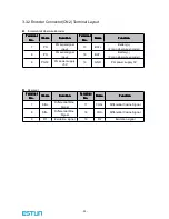
3.2.3 I/O Signal Connector (CN1) Terminal Layout
Note:
Note:
Note:
Note:
The functions allocated to the following input and output signals can be changed by using the
parameters.
·Input signals: /S-ON
,
/P-CON
,
P-OT
,
N-OT
,
/ALM-RST
,
/CLR
,
/PCL
,
/NCL
·Output signals: /TGON
,
/S-RDY
,
/COIN
Please refer to
A.3
A.3
A.3
A.3 Parameters
Parameters
Parameters
Parameters in
in
in
in details
details
details
details
for detailed information.
Terminal
Terminal
Terminal
Terminal
No.
No.
No.
No.
Name
Name
Name
Name
Function
Function
Function
Function
Terminal
Terminal
Terminal
Terminal
No.
No.
No.
No.
Name
Name
Name
Name
Function
Function
Function
Function
1
VREF+
Speed reference input:±10V
26
T-REF+
Torque reference
input:±10V
2
VREF-
27
T-REF-
3
AGND
AGND
28
AGND
AGND
4
—
Reserved
29
—
Reserved
5
/TGON+
Running signal output
30
PULS+
Reference pulse input
6
/TGON-
31
PULS-
7
ALM+
Servo alarm
32
SIGN+
Reference sign input
8
ALM-
33
SIGN-
9
/S-RDY+
Servo ready
34
PPI
Open collector
reference power supply
10
/S-RDY-
35
—
Reserved
11
/COIN+
Positioning completion
36
—
Reserved
12
/COIN-
37
—
Reserved
13
DICOM
I/O signal power supply 24V
DC
38
—
Reserved
14
/S-ON
Servo ON
39
/ALM-
RST
Alarm reset
15
/P-CON
P/PI control input
40
/CLR
Position error pulse
clear input
16
P-OT
Forward run prohibit input
41
/PCL
Forward torque limit
input
17
N-OT
Reverse run prohibit run
42
/NCL
Reverse torque limit
input
18
—
Reserved
43
—
Reserved
19
—
Reserved
44
—
Reserved
20
PAO+
PG dividing
pulse output
phase A
PG dividing
pulse
output
45
—
Reserved
21
PAO-
46
DGND
DGND
22
PBO+
PG dividing
pulse output
phase B
47
—
Reserved
23
PBO-
48
DGND
DGND
24
PCO+
PG dividing
pulse output
phase C
Zero-point
pulse
49
—
Reserved
25
PCO-
50
DGND
DGND


