background image

USER MANUAL > CENTERING A LENS

Mr Blue 2.0 > v4.0 -09.16

65

8

7

6

5

4

3

2

1

8

7

6

5

4

3

2

1

8

7

6

5

4

3

2

1

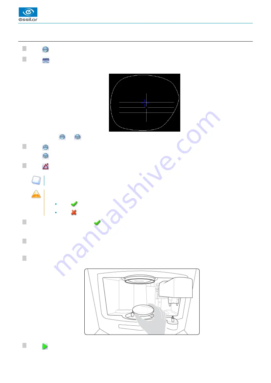
a. Centering an executive lens in automatic mode

Press 

 to select the type of executive lens.

Press 

 to select the automatic centering mode.

Press 

 to do a far vision centering.

Press 

 to do a near vision centering.

Press 

 to enter the cylinder angle (if the lens has one).

This  information  makes  it  possible  to  straighten  the  lens  perfectly  at  the  angle  required  by  the  prescription,  then
ensure that the posiblock is set on the same axis.

When you start the blocking of a cylindrical lens without having indicated the angle value, a warning is displayed at
the start of the blocking operation:

Press 

 if you don't want to change the default value (default value = 0°).

Press 

 if you want to modify this value. The numeric keypad is displayed.

Enter the desired value, then press 

 to confirm.

Enter the half-PD and pupillary height (for far vision or near vision, depending on your selection).

Position the lens in the centering chamber.

Press 

 to start centering.

The centering target is displayed:

>

Two buttons 

 and 

 appear for each eye (right eye/left eye) on both sides of the work area.

>

The angle value is displayed in the centering screen.

>

The target moves.

>

Содержание Mr Blue 2.0

Страница 1: ...User Manual ...

Страница 2: ......

Страница 3: ...g environment 39 a Menu screen 39 b Centering modes 41 2 Centering a single vision lens 42 a Centering a single vision lens in automatic mode 43 b Centering a single vision lens using three focimeter dots 45 c Centering a single vision lens using re marked micro engravings 48 d Lens fit function 50 e Centering a single vision lens in manual mode 51 3 Centering a progressive lens 52 a Centering a p...

Страница 4: ...point 97 d Adjusting the position of a drilling point 98 3 Drilling models 101 a Importing a model 101 b Saving a model 102 VI PREPARING LENS EDGING 103 1 Menu screen 105 2 Edging settings 106 VII TRACER CENTERER BLOCKER CONFIGURATION 109 1 Configure the tracer centerer blocker 111 a Time date and language 111 b Connections 111 c Screensaver 113 2 Customize the tracer 113 a Working mode and measur...

Страница 5: ...CHNICAL DATA 139 1 Tracer centerer blocker 140 2 Environment 141 GENERAL INFORMATION 143 1 Symbols 144 2 Modifications 144 3 Declaration of conformity 144 4 Copyright 144 5 Materials and products 144 6 Safety instructions 145 7 Electromagnetic waves 145 8 License agreement for M EYE Sign Engraving software 145 a General information 145 b Accepted use of the Software and restrictions 145 c Liabilit...

Страница 6: ...USER MANUAL CONTENTS ...

Страница 7: ...ith re marked micro engravings for the single vision lenses the prp is set by default at 0 The edging preparation screen menu and the edger selection page associated with the product are accessible and configurable on the customization screen An Essibox button is available on all the products on the tracing centering and finishing page The modification of IP settings is accessible it is from now p...

Страница 8: ...USER MANUAL INTRODUCTION 8 Mr Blue 2 0 v4 0 09 16 ...

Страница 9: ...I FIRST STEPS WITH MR BLUE 2 0 ...

Страница 10: ...USER MANUAL FIRST STEPS WITH MR BLUE 2 0 10 Mr Blue 2 0 v4 0 09 16 ...

Страница 11: ...ng the device p 13 1 Descriptive diagrams This section consists of descriptions and the list of accessories of the tracer centerer blocker Screen ON OFF button Pattern holder Operating accessory hatch Centering chamber Protective glass Tracing table Pad dispenser Posiblock dispensers on both sides of the screen Service accessory hatch Blocking arm Indexer Access to roll of pads Screen tilt buttons...

Страница 12: ... cover Pattern holder Bag of 22 mm posiblocks Bag of 18x14 mm posiblocks Transport wedges to be kept Operating accessory hatch High base tripod Recut lens tripod Stylus Small B dimension wedges quantity 2 White felt tip marker Service accessory hatch Calibration posiblock Pattern gauge metal Frame gauge black numbered CD ROM of calibration gauge data Lower hatches Roll of 22 mm pads Roll of 18 x 1...

Страница 13: ...e work screen tracer p 15 a Turning on the tracer centerer blocker Before you switch on the tracer make sure the tracing table is empty To switch on the tracer press the main switch located at the rear of the machine The tracer may be switched on independently if you only want to do successive tracings Press the ON OFF button located under the touch screen To ensure maximum precision and efficienc...

Страница 14: ...not sensitive enough to finger pressure press lightly with a fingernail If the response area does not correspond to the position of the key you need to calibrate the touch screen For more information refer to the following section Maintenance and servicing Checks and calibration Calibrating the touch screen p 125 Never press hard on the screen as this could break it Never press on the screen with ...

Страница 15: ...2 0 v4 0 09 16 15 1 2 3 4 5 Job ID Job reference alphanumeric characters list jobs p 148 Collection list d Tracing screen Work screen indicator Saved jobs list Job list Collection list Information on the job and working mode Settings Devices connected ...

Страница 16: ...e left for a left lens Binocular display Function button Tracer menu Machine shutdown Tracing screen Centering screen Shape management screen Edging preparation accessible according to the configuration chosen for more information consult the chapter Set up the tracer centerer blocker Customize the tracer Work mode and display of measurements p 113 Job call on Essibox Actions available for the cur...

Страница 17: ...II TRACING ...

Страница 18: ...USER MANUAL TRACING 18 Mr Blue 2 0 v4 0 09 16 ...

Страница 19: ...acing a high base frame p 28 Tracing a pattern a demo lens or recut lens p 30 1 The tracing environment This section describes the tracing screen and explains how to manage the jobs Description of the tracing screen p 19 Jobs and working modes p 21 Displaying the tracing completed in binocular mode p 21 a Menu screen Dimensions display A A dimension B B dimension D D dimension E Larger radius from...

Страница 20: ... with feeling of the groove Plastic frame Optyl for particularly flexible frames frame p 149 For optical tracing Demo lens Recut lens for frame typeNylor Demo lens Recut lens for drilled frame Pattern For mechanical tracing of demo lenses recut lenses or patterns the tracer automatically detects the pattern holder inserted in the tracing table Groove detection insertion in the middle of the frame ...

Страница 21: ...gs Working in the tracing centering mode After tracing the tracer automatically displays the centering screen You can fully process a job before proceeding to the following Tracing or recovering a job from the database Changing the shape and drilling position if necessary Centering Lens blocking Lens edging Working in the tracing tracing mode After tracing the tracer displays the tracing screen ag...

Страница 22: ... is displayed again once tracing is complete Press to display the binocular view The binocular view is displayed Position the frame in front of the screen against the faceplate to check its shape and centering Press to return to the monocular screen 2 Shape management and storage This section explains how to manage the available lists to store your shapes Description of the shape storage screen p ...

Страница 23: ...o lens or recut lens Job counter for the selected list Back to the default display of the selected list Display all jobs starting with the selected letter To display the all jobs starting with the selected letter Press once if it is in the first position on the button Press twice in succession if it is in the second position Press three times in succession if it is in the third position Example Pr...

Страница 24: ...via the button The job list The job list enables you to save jobs on a daily basis without the possibility of re using them at a later date It can store up to 1 000 jobs The collection list The collection list enables you to save specific jobs for subsequent re use Recurrent jobs Standard shapes Drilling models It can store up to 1 000 jobs The barcode reader optional cannot be used to call or sav...

Страница 25: ...b ID if the right lens has been blocked but not the left If you don t want to save the job you can work in current job mode For more information refer to the following section Tracing Shape management and storage Working in current job mode job A p 25 Successive tracings and saving If you start a new tracing while a job is still active on the tracing screen a message is displayed Replacement of th...

Страница 26: ... ID can consist of alphanumeric characters In the collection list the ID solely consists of numeric characters Press to enter the reference of the new job Irrespective of the list selected the reference may consist of alphanumeric characters It can contain the information of your choice Customer s name Frame brand or reference Manufacturer etc Press to confirm Job list Collection list The tracer i...

Страница 27: ...ng table between the two clamps located opposite you Gently close the jaw to hold the frame Optyl p 149 frames take care not to flatten the frame by closing the jaws Press to select the type of rimmed frame Select the required type of tracing Select the frame material Select the type of groove insertion medium high or low As part of the tracing of an asymmetrical groove frame sport or safety frame...

Страница 28: ...is specific procedure enables you to trace a high base frame if the standard rimmed frame tracing fails Tracing of a high base frame is done in two stages The frame is placed in the tracing table and mechanical tracing is done for each eye individually The curve angle is measured and the tracing is completed Put the frame in place and start the tracing When you place the frame in the tracing table...

Страница 29: ...ed in a monocular tracing Place the frame on the screen The vertical blue line must be in the center of the frame The plane which is tangent to the two lenses must coincide with the pink line at the bottom If the frame doesn t stay straight you can tilt the screen slightly by pressing the two side buttons at the back of the screen Use the and buttons to align the light blue lines with the nasal an...

Страница 30: ...urve angle and frame base which cannot be captured in this type of tracing Optical tracing p 30 Mechanical tracing p 32 Inputting the curve and the frame base after monocular tracing p 34 a Optical tracing Preparing optical tracing of demo or recut lens This type of tracing makes it possible to retrieve the existing shape and drilling data of a lens Prerequisite for the tracer to correctly detect ...

Страница 31: ...environment Jobs and working modes p 21 Before Centering Once tracing has been carried out you can Input the curve angle and the frame base for optimal centering precision Modifying the lens shape For more information consult the chapter Modifying the lens shape p 83 Add drilling points on the shape For more information consult the chapter Preparing a drilled job p 91 If the tracer does not detect...

Страница 32: ...e pattern holder Block the lens in the boxing center making sure it is properly centered Insert the blocked lens in the posiblock clamp holding it in position with your index finger Press on the knurled button screwing until the blocked lens is immobilized The feeling pressure on the lens being weak it is pointless to excessively screw down the knurled button Attaching a pattern to the pattern hol...

Страница 33: ...ewing of the knurled knob inside the posiblock of the nozzle has no functional impact on the latter Place the pattern holder in the tracing table Insert the front tab of the support between the white cylindrical studs of the tracing table Block the back tab of the support Adjust the jaws of the tracing table so as to block the pattern holder Start the cycle Release the pressure on the white circle...

Страница 34: ...r tracing In a monocular tracing the curve angle and frame base cannot be measured For optimal centering precision we recommend that you enter those values after the optical or mechanical tracing of a pattern recut lens or demo lens Prerequisite before entering the curve angle and frame base one of the following operations must be performed Optical tracing of a pattern a demo lens or a recut lens ...

Страница 35: ...ght blue lines with the nasal and temporal ends of the rims You can also press for a few seconds on the value and change it using the numeric keypad Select the frame base value to modify it Use the and buttons to modify the frame base value You can also press for a few seconds on the value and change it using the numeric keypad Press to confirm The value of the curve angle is modified The value is...

Страница 36: ...USER MANUAL TRACING 36 Mr Blue 2 0 v4 0 09 16 ...

Страница 37: ...III CENTERING A LENS ...

Страница 38: ...USER MANUAL CENTERING A LENS 38 Mr Blue 2 0 v4 0 09 16 ...

Страница 39: ...t out of the tracer centerer blocker and take advantage of all its features we recommend that you follow the advice below Eliminate any source of light natural or artificial pointing directly towards the centering chamber to avoid interfering with lens measurement and centering Check that the lenses are clean before proceeding with automatic centering Hartmann plate protective glass Clean the wind...

Страница 40: ...mation refer to the section Configuring the digital system Customizing the tracer Working mode and display of measurements p 113 Lens type selection Single vision lens p 149 Progressive lens p 149 Bifocal lens p 149 Executive lens p 148 Mid distance lens p 149 Centering mode selection Automatic centering Centering using three focimeter dots Centering using re marked micro engravings Centering usin...

Страница 41: ... available while others will not b Centering modes The centering modes available depend on the selected lens type Always refer to the specific procedure for your type of lens Using the tripods Two accessories are available to ensure better stability of high curve lenses and small lenses In the centering chamber you can thus place the high base lens tripod p 149 the recut lens tripod p 149 ...

Страница 42: ...is displayed Put the lens back in place and press The centering resumes To avoid all interference with the Hartmann plate calibration place the lens in the centering chamber just before you start the centering 2 Centering a single vision lens Prerequisite Before centering the lens you must first trace a shape in the centering screen If necessary we recommend the following prior operations Modifyin...

Страница 43: ...s it possible to straighten the lens perfectly at the angle required by the prescription then ensure that the posiblock is set on the same axis When you start the blocking of a cylindrical lens without having indicated the angle value a warning is displayed at the start of the blocking operation Press if you don t want to change the default value default value 0 Press if you want to modify this va...

Страница 44: ...ens outside the shape is displayed in red To get the shape to fit into the lens you can Use the lens fit function For more information refer to the section Centering a lens Centering a single vision lens Lens fit function p 50 Modify the PD and pupillary height If modifying the PD and pupillary height results in too great an induced prism we advise you to order a new lens in the proper diameter Th...

Страница 45: ...lens must be marked with the focimeter The three focimeter dots must be Lined up At the same distance from the central dot 0 5 to 1 5 mm in diameter Centering the lens Add a mark to enable the tracer to distinguish the top of the lens The top of lens mark must be located in the upper part of the lens be positioned 1 to 2 cm above the focimeter dots be a thick shape contained in a 1 cm square The s...

Страница 46: ...s the centering is perfect Display of the optical center of the lens white cross and boxing center of the shape blue cross Display of the sphere power Display of the cylinder power The cylinder angle is displayed The lens base is displayed The target moves The clamps close on the lens to hold it in position until its blocking The lens analysis starts the tracer searches for the optical characteris...

Страница 47: ...he lens you can Use the lens fit function For more information refer to the section Centering a lens Centering a single vision lens Lens fit function p 50 Modify the PD and pupillary height If modifying the PD and pupillary height results in too great an induced prism we advise you to order a new lens in the proper diameter To carry out lens blocking refer to the section Centering a lens Blocking ...

Страница 48: ...dvise you to use the white felt tip marker supplied with the tracer to mark the lens an alcohol based solution such as Essiclean to remove existing markings TM Press to select the type of single vision lens Press to select the centering mode starting at the micro engravings Enter the half PD and pupillary height Enter the half PD and pupillary height If necessary modify the distance between the PR...

Страница 49: ... clamps it must not be handled To stop centering at any time press The clamps close on the lens to hold it in position until its blocking The lens analysis starts the tracer searches for the optical characteristics of the lens The centered lens is displayed in the work area The lens is centered and ready to be blocked ...

Страница 50: ... mode or using three focimeter dots Refer to the sections and Centering a single vision lens Automatic mode p 43 Centering a single vision lens Three focimeter dots mode p 45 It enables you to limit the induced prism and ensure a quality job Once the lens has been centered if part of the shape representing the frame rim is outside the lens diameter it is indicated in red Modifying the pupillary ha...

Страница 51: ...sion lens Press to select the manual centering mode Enter the half PD and pupillary height Position the lens on the clamps and center it in keeping with the target You can control the opening and closing of the clamps for better control of the stability of the lens Press to open the clamps Press to close the clamps As soon as you place the marked lens on the clamps the tracer automatically detects...

Страница 52: ... p 91 to be created Place the stickers recommended by the manufacturer on hydrophobic lenses This section describes the procedures for the centering of a progressive lens Centering using re marked micro engravings p 53 Centering using manufacturer markings mode p 55 Centering in manual mode p 57 Do not center the thickness 0 8 mm in manufacturer markings mode or in re marked precalibrated lenses p...

Страница 53: ...upplied with the tracer to mark the lens an alcohol based solution such as Essiclean to remove existing markings TM Second option Mark the micro engravings after having removed all original marks Remark each micro engraving with a felt tip marker The diameter of the dots must be between 0 5 and 1 mm Around the two micro engravings draw a circle with a diameter of 5 to 10 mm Keep or redraw the near...

Страница 54: ...lor progressive lenses This value may vary depending on lens manufacturers Position the lens in the middle of the centering chamber Press to start lens tracing Once the lens is held by the clamps it must not be handled To stop centering at any time press The centering target is displayed The target moves The clamps close on the lens to hold it in position until its blocking The lens analysis start...

Страница 55: ...s but if the induced prism is too great we advice you to order a new lens in the proper diameter To carry out lens blocking refer to the section Centering a lens Blocking a lens p 80 b Centering a progressive lens using manufacturer markings mode Prerequisite The markings must be clear The lens must at least have the following markings If the lens doesn t meet the criteria described above we advis...

Страница 56: ...progressive lens Press to select automatic centering using manufacturer markings Enter the half PD and pupillary height Position the lens in the middle of the centering chamber Press to start lens tracing Once the lens is held by the clamps it must not be handled To stop centering at any time press The centering target is displayed The target moves The clamps close on the lens to hold it in positi...

Страница 57: ...7 Lens fit check A visual warning enables you to check the lens fit any part of the lens outside the shape is displayed in red You can modify the PD and pupillary height to get the shape to fit into the lens but if the induced prism is too great we advice you to order a new lens in the proper diameter To carry out lens blocking refer to the section Centering a lens Blocking a lens p 80 c Centering...

Страница 58: ...cross present on the lens must be superimposed on the target centering cross Make sure that the target centering marks line up with the lens centering marks To carry out lens blocking refer to the section Centering a lens Blocking a lens p 80 4 Centering bifocal trifocal lenses Prerequisite Before centering the lens you must first trace a shape in the centering screen If necessary we recommend the...

Страница 59: ...type of bifocal lens Press to select the automatic centering mode Press to enter the cylinder angle if the lens has one This information makes it possible to straighten the lens perfectly at the angle required by the prescription then ensure that the posiblock is set on the same axis When you start the blocking of a cylindrical lens without having indicated the angle value a warning is displayed a...

Страница 60: ...on display Lens fit check A visual warning enables you to check the lens fit any part of the lens outside the shape is displayed in red You can modify the PD and pupillary height to get the shape to fit into the lens but if the induced prism is too great we advice you to order a new lens in the proper diameter To carry out lens blocking refer to the section Centering a lens Blocking a lens p 80 Th...

Страница 61: ...iameter For bifocal lenses with a round segment first remove any manufacturer markings Centering the lens Press to select the type of bifocal lens Press to select the automatic centering mode from three focimeter dots Enter the half PD and pupillary height for far vision Position the lens in the middle of the centering chamber Press to start lens tracing Once the lens is held by the clamps it must...

Страница 62: ...80 c Centering a bifocal lens in manual mode Manual centering enables you to center the lenses which cannot be centered in automatic mode cannot be centered automatically using the three focimeter dots In this mode the lens is centered in near vision Prerequisite The lens must be marked with the focimeter The three focimeter dots must be Lined up At the same distance from the central dot 0 5 to 1 ...

Страница 63: ...u can control the opening and closing of the clamps for better control of the stability of the lens Press to open the clamps Press to close the clamps You can choose to center the lens on the protective glass open the clamps completely Do not manually center the thickness 0 8 mm directly on the window The precalibrated lenses p 149 lenses would be liable to break during blocking Take care not to d...

Страница 64: ...e following prior operations Modifying or retouching the traced shape p 83 Preparing drilling points p 91 to be created Place the stickers recommended by the manufacturer on hydrophobic lenses This section describes the procedures for the centering of an executive lens Centering in automatic mode p 65 Centering using three focimeter dots p 66 Centering in manual mode p 68 Do not center the thickne...

Страница 65: ...t on the same axis When you start the blocking of a cylindrical lens without having indicated the angle value a warning is displayed at the start of the blocking operation Press if you don t want to change the default value default value 0 Press if you want to modify this value The numeric keypad is displayed Enter the desired value then press to confirm Enter the half PD and pupillary height for ...

Страница 66: ... diameter To carry out lens blocking refer to the section Centering a lens Blocking a lens p 80 b Centering an executive lens using three focimeter dots In this mode the lens is centered in far vision Prerequisite The lens must be marked with the focimeter The three focimeter dots must be Lined up At the same distance from the central dot 0 5 to 1 5 mm in diameter Centering the lens Press to selec...

Страница 67: ...e centering chamber Press to start lens tracing Once the lens is held by the clamps it must not be handled To stop centering at any time press The centering target is displayed The target moves The clamps close on the lens to hold it in position until its blocking The lens analysis starts the tracer searches for the optical characteristics of the lens ...

Страница 68: ...an executive lens in manual mode Manual centering enables you to center the lenses which cannot be centered in automatic mode cannot be centered automatically using the three focimeter dots Prerequisite The lens must be marked with the focimeter The three focimeter dots must be Lined up At the same distance from the central dot 0 5 to 1 5 mm in diameter Description of the centering target Optical ...

Страница 69: ...segment between near vision and far vision with the horizontal mark in the center Position the central focimeter dot on the vertical axis of the target To carry out lens blocking refer to the section Centering a lens Blocking a lens p 80 6 Centering a mid distance lens Prerequisite Before centering the lens you must first trace a shape in the centering screen If necessary we recommend the followin...

Страница 70: ...ENTERING A LENS 70 Mr Blue 2 0 v4 0 09 16 Do not center the thickness 0 8 mm in manufacturer markings mode or in re marked precalibrated lenses p 149 micro engravings mode you are likely to break them with blocking ...

Страница 71: ...he manufacturer marking forms two circles around the micro engravings erase them before marking the lens with a felt tip marker We advise you to use the white felt tip marker supplied with the tracer to mark the lens an alcohol based solution such as Essiclean to remove existing markings TM Press to select the type of mid distance lens Press to select automatic centering using re marked micro engr...

Страница 72: ... but if the induced prism is too great we advice you to order a new lens in the proper diameter To carry out lens blocking refer to the section Centering a lens Blocking a lens p 80 b Centering a mid distance lens using manufacturer markings mode Prerequisite The markings must be clear The lens must at least have the following markings The clamps close on the lens to hold it in position until its ...

Страница 73: ... mid distance vision Centering marks for near vision Mid distance vision Centering cross Near vision Centering the lens Press to select the type of mid distance lens Press to select automatic centering using manufacturer markings Enter the half PD and pupillary height for near vision Position the lens in the middle of the centering chamber The centering target is displayed The target moves ...

Страница 74: ... Markings database p 77 Lens fit check A visual warning enables you to check the lens fit any part of the lens outside the shape is displayed in red You can modify the PD and pupillary height to get the shape to fit into the lens but if the induced prism is too great we advice you to order a new lens in the proper diameter To carry out lens blocking refer to the section Centering a lens Blocking a...

Страница 75: ...enter it in keeping with the target You can control the opening and closing of the clamps for better control of the stability of the lens Press to open the clamps Press to close the clamps You can choose to center the lens on the protective glass open the clamps completely Do not manually center the thickness 0 8 mm directly on the window The precalibrated lenses p 149 lenses would be liable to br...

Страница 76: ...re that the center of the wearer s pupil is at the optical center of the lens For an optimal job the on screen positioning of the centering indicators always takes account of 3D compensation Match between frame base and lens base To do a job involving a high base frame use lenses whose base matches that of the frame maximum difference of 0 7 D Refer to the centering procedure for the particular ty...

Страница 77: ...enu screen To access the markings database select in the information bar then The following screen is displayed IDs of the markings Press to sort the markings by ID References of the markings Press to sort the markings by reference in ascending order press again to sort them in descending order Active eye Select the eye to view the corresponding marking Display the selected marking Add a new marki...

Страница 78: ...erent To record the markings use low power lenses up to 3 D Carefully clean the lens before recording the marking Select lenses with clear and complete markings make sure there are no interfering marks Press Enter an ID and the reference of your new marking The first free slot in the database is proposed by default You can modify the ID if you wish Press to confirm Position the lens in the centeri...

Страница 79: ...k corresponding to near vision Position the yellow cross on the point corresponding to near vision using the virtual mouse Now record the data for the second eye Press once the right eye and left eye markings have been saved The left centering mark is selected A green cross appears in the target The right centering mark is selected A red cross appears in the target The recording of the first eye i...

Страница 80: ... frame and the posiblock you choose to use certain finishes may or may not be possible In such cases an alert is displayed Example Press and block the lens with an 18 14 mm posiblock to do a high base bevel and or chamfer Otherwise press and block the lens with a 22 mm posiblock Fit the appropriate pad on the posiblock The fins of the posiblock must remain visible The tab of the pad must be lined ...

Страница 81: ...rrespond to the characteristics of the job a warning is displayed press and restart the blocking operation If the pad is stuck the wrong way round a warning is displayed We recommend that you restart the blocking operation press For a hydrophobic lens press with your fingers on the posiblock so that it adheres to the lens properly The adjustments made to the PD pupillary height type of lens and ce...

Страница 82: ...USER MANUAL CENTERING A LENS 82 Mr Blue 2 0 v4 0 09 16 ...

Страница 83: ...IV MODIFYING THE LENS SHAPE ...

Страница 84: ...USER MANUAL MODIFYING THE LENS SHAPE 84 Mr Blue 2 0 v4 0 09 16 ...

Страница 85: ...ith the shape traced and associated drilling points light red Shape before modification grey Part of the shape not selected for the modification underway purple Smallest possible shape pink Limit of the no accessory area yellow Limit of the drilling area red Non machinable shape blue Reference drilling points green Lens already blocked Binocular view Half PD and pupillary height Active eye The sel...

Страница 86: ...ining to lens edging The in the event of possible tracing defects retouching of a shape p 89 Any modification or retouch of the shape must be performed before centering the lens Shape modifications and retouches are only applied if all the dimensions and half dimensions limits are included If a portion of the shape is not included within the machinable limits it is displayed in red a Enlarging red...

Страница 87: ...ress for a few seconds on the corresponding value to display the numeric keypad enter a new value and press to confirm Example of a total enlargement of the shape Rotating a shape around the boxing center Press to select modification by rotation Use the buttons or to rotate the shape clockwise or anti clockwise by 1 and view the modification in real time The shape is modified The original shape is...

Страница 88: ... both eyes simultaneously Modification of each eye separately In symmetric monocular or binocular tracing modifications are automatically made to both eyes Select Select the type of modification Modification focused on the center of the selected area Uniform modification across all points of the selected area Modification directed towards the two ends of the selected area Drag the cursors and to d...

Страница 89: ...g you can modify both shapes simultaneously Modification of both eyes simultaneously Modification of each eye separately In symmetric monocular or binocular tracing modifications are automatically made to both eyes Select Drag the cursors and to delimit the selection area Select the type of retouch The types of retouch available vary according to the size of the selected area Retouch to create a s...

Страница 90: ...ing a shape This function enables you to save a modified shape to a new job with a new ID while keeping the original job Press Select the list in which you want to store the shape Job list Collection list You can also give it a different ID Enter a reference for the shape to be saved Press to confirm The job creation alphanumeric keypad is displayed A new ID is allocated first free slot in the sel...

Страница 91: ...V PREPARING A DRILLED JOB ...

Страница 92: ...USER MANUAL PREPARING A DRILLED JOB 92 Mr Blue 2 0 v4 0 09 16 ...

Страница 93: ... is complete Glass lenses The drilling function is not available for glass lenses 1 Legend screen In the centering screen press to access the drilling screen The following screen is displayed Work area Colours which may appear on screen white Current shape stemming from the shape scanned and associated drilling points cyan Current shape obtained by symmetry with the shape scanned and associated dr...

Страница 94: ... one or all drilling points Delete one drilling point Delete all drilling points Photo mode Acts as an aid to manually position the holes on a shape as part of the mechanical tracing of a power lens a demo lens or a pattern Zoom Create and set the drilling points for both eyes simultaneously Symmetrically transfer the drilling points from the nasal to the temporal side or vice versa Modify the sel...

Страница 95: ...ing points simultaneously on both shapes Create or modify drilling points for both eyes simultaneously Create or modify drilling points for each eye separately In monocular or symmetric binocular tracing the drilling points are automatically positioned on both eyes you can however manage the drilling points on the left side independently of the right side press drilling points are no longer linked...

Страница 96: ... shape Photo mode After tracing a pattern it is possible to retrieve the drill holes on the corresponding demo lens Position the demo lens corresponding to the pattern in the centering chamber press For photo mode it is not necessary to mark the lens the posiblock can also be kept it is a simple shot If the image is badly centered repeat the operation Manually position the drill holes of the shape...

Страница 97: ...existing drilling point Press on the drill hole slot or notch to select it Press a few seconds on the setting to be modified Diameter Depth for non through holes Length of slot or notch Angle of slot or notch You can also use the buttons or to reduce or increase the selected value Enter the new setting then press to confirm The drilling point is displayed in red Two buttons are displayed The selec...

Страница 98: ...same way only the reference drilling point is modifiable the coordinates of the other drilling points are greyed out To ungroup the drilling points press again on d Adjusting the position of a drilling point You have three options for adjusting the position of a drilling point on a shape Use the virtual mouse Use the buttons or to reduce or increase the selected value Input the exact coordinates o...

Страница 99: ... seconds on the value corresponding to the coordinates to be modified X coordinates Y coordinates Distance from the edge of the lens X coordinates in relation to the reference drilling point Y coordinates in relation to the reference drilling point Freeze the distance to the edge of the lens and adjust only the Y position of the drilling point Enter the new value then press to confirm The drilling...

Страница 100: ...lling points are greyed out To ungroup the drilling points press again on Reference drilling point The first drilling point you set on a shape automatically becomes the reference drilling point in relation to which you will be able to position the other ones Each side nasal and temporal has its reference drilling point identified by its dark blue colour It is identified by the symbol on the left o...

Страница 101: ...The height of the drilling points in relation to the center of the shape Y coordinates The distance between the reference drilling point and the edge of the lens In the drilling point positioning screen press to access the list of drilled jobs saved in the shape management screen Select the desired list Select the desired job as a drilling model Press to confirm the import of the model The setting...

Страница 102: ...ables you to save in a new job The traced shape The value of the D dimension The drilling point settings The drilling point heights in relation to the Boxing center of the shape Y coordinates The distance from reference drilling points in relation to the edge of the lens other drillings in relation to reference drilling Press to save the drilling points you have just configured to the current job ...

Страница 103: ...VI PREPARING LENS EDGING ...

Страница 104: ...USER MANUAL PREPARING LENS EDGING 104 Mr Blue 2 0 v4 0 09 16 ...

Страница 105: ...en For more information consult the chapter Setting up the tracer centerer blocker customizing the tracer work mode and display of measurements p 113 1 Menu screen Press to access the edging preparation screen The following screen is displayed Lens material Plastic lensindex 1 5 p 149 Polycarbonate lens Medium High index plastic lens index 1 5 Trivex lensTM Glass lens TribridTM The configuration o...

Страница 106: ...ion acquired when tracing the frame and feeling the lens Customized mode The finish settings can be fully customized Polishing Polished lens Non polished lens Front surface chamfering Small chamfer Large chamfer No chamfering Rear surface chamfering Small chamfer Large chamfer No chamfering Displaying the binocular view Save the settings Return to the centering screen 2 Edging settings You can inp...

Страница 107: ...edging mode Press to activate deactivate polishing Press to select back chamfering Press to select front chamfering Press to memorize the parameter setting and go back to the centering screen or the tracing screen if the option is activated When you call the shape from the edger its edging settings will be automatically recovered ...

Страница 108: ...USER MANUAL PREPARING LENS EDGING 108 Mr Blue 2 0 v4 0 09 16 ...

Страница 109: ...VII TRACER CENTERER BLOCKER CONFIGURATION ...

Страница 110: ...USER MANUAL TRACER CENTERER BLOCKER CONFIGURATION 110 Mr Blue 2 0 v4 0 09 16 ...

Страница 111: ...age p 111 Access the connections and the network p 111 Configure a screensaver p 113 a Time date and language To access this menu from your work screen select The following screen is displayed Time Use the arrows and to set the time Date Use the arrows and to set the date Type of date display Select the type of display out of the available formats Language Select the flag corresponding to your lan...

Страница 112: ...ss preset before leaving the factory unchangeable Addressing mode Static mandatory if the machines are connected to one another DHCP the addressing settings of the optician s network have been recovered Ethernet network settings IP IP address preset before leaving the factory MASK subnet mask preset before leaving the factory GATEWAY gangway never fill out DNS1 by default the DNS 1 address server ...

Страница 113: ... transition time between each image in seconds Once the modification has been made press to go back to the work screen 2 Customize the tracer This section will enable you to customize the tracer according to your requirements Choose a Working mode a measurement display mode and set up the functions p 113 Choosing a decentration mode p 115 Customising the action bar p 115 a Working mode and measure...

Страница 114: ... of the progressive lenses you work with Enter the PRP value according to the specific features of the Interview lenses you work with Cylinder angle Select the step to be applied for the data entry of the cylinder angle Sphere and cylinder display Select the step to be applied for the display of the sphere and cylinder measurement Addition Select the step to be applied for the display of the addit...

Страница 115: ...nter of the shape and the center of the wearer s pupil ΔY This value corresponds to the difference in height between the boxing center of the shape and the center of the wearer s pupil Once the modification has been made press to go back to the work screen c Action bar This menu enables you to customize the action bar according to your requirements You can deactivate certain options that you do no...

Страница 116: ...g mode Demo lens for Nylor frame Recut lens Pattern Demo lens for drilled frame Recut lens Automatic detection of the type of demo lens pattern Groove detection The menu is displayed and selected by fault in the action bar Automatic detection default setting systematically carried out on the metal frames Groove detection never carried out Groove detection carried out systematically The menu is dis...

Страница 117: ...ion up to 25 of frame height high insertion up to 75 of frame thickness Press to move to the next page Press The following screen is displayed Type of lens Single vision lens Progressive lens Bifocal lens Executive lens Mid distance lens Interview Press to go back to the first page Press to move to the next page Press The following screen is displayed ...

Страница 118: ...r Automatic connection Manual connection Once the modifications are made press to go back to the work screen 3 Restore the factory settings At the bottom right of certain settings screens the button enables you to restore the page s factory settings Press to cancel and go back to the settings screen Press to confirm the reset ...

Страница 119: ...VIII MAINTENANCE SERVICING ...

Страница 120: ...USER MANUAL MAINTENANCE SERVICING 120 Mr Blue 2 0 v4 0 09 16 ...

Страница 121: ... tracer p 132 1 Carrying out the autotests This menu is used for auto diagnosis of the tracer functions Tracing table To test the operation of the tracing table select from your work screen Tracing table autotests Clamps Vertical movement of the feeler Rotation of tracer core Displacement of tracer core Feeler movement Select the autotest to be carried out Press to start the test cycle You can pre...

Страница 122: ...You can press to stop the cycle at any moment The result is displayed on the right of the icon of the autotest carried out The equipment is operational A malfunction has been detected a description is displayed in the message box on the right 2 Checks and calibration This section describes the procedures to follow if you notice mounting problems that may be due to tracing or centering operations C...

Страница 123: ...ical department Select Insert the pattern gauge in the tracing table Press to start the test Wait a timer is displayed for a few minutes The test is successful press to go back to the work screen The test has failed start a calibration cycle Calibration This procedure must be followed if the above calibration test has failed Select to start the cycle Attach the pattern gauge to the pattern holder ...

Страница 124: ...check the calibration of the centering chamber and blocking arm From the work screen of your tracer select The following screen is displayed Checking the posiblock grasp Place the calibration posiblock on the indexer Select the test and press to start the cycle The blocking arm moves to grasp the calibration posiblock it does a series of movements coming into contact with the indexer several times...

Страница 125: ...on Press to start the cycle An information message is displayed Place the calibration posiblock on the blocking head Press to confirm Wait the blocking arm performs a series of movements The calibration is finished Calibrate the centering device Select the calibration Press to start the cycle An information message is displayed Place the calibration posiblock on the blocking head Press to confirm ...

Страница 126: ... Press to cancel and go back to the menu Point precisely on each cross as they are displayed holding the stylus perpendicular to the screen so as not to alter the calibration Press to go back to the work screen A confirmation message is displayed The settings menu is displayed automatically once the calibration is finished ...

Страница 127: ...data Jobs and display customisation Press to select the action to perform perform a backup import a backup Click on to backup the customization of the tracer display Press to start the operation Product number L14XXX Product serial number XXXXXX Optician Date XX XX XXXX Time XXhXXmXXs Example It is advisable to backup your jobs regularly The following screen is displayed Once the backup is perform...

Страница 128: ...ion If several backups are present on the key take care to choose the one you want to restore Check the product serial number and the date and time of backup Press to start the operation Remove the USB key 4 Remote control Function As part of a maintenance operation your technical correspondent can remotely control your machine Check the tracer s connection to the Internet Press The backup screen ...

Страница 129: ...NG Mr Blue 2 0 v4 0 09 16 129 1 3 2 Press Press to confirm If Internet connection is not correct contact your customer support Start a session of remote maintenance Press The following screen will appear The following message appears ...

Страница 130: ...rt the session of remote maintenance A green frame appears around the screen Note the number which is displayed in the center of the screen and communicate it to your technical correspondent Once the connection is established a red frame appears around the screen Press to end the session The product page is displayed The following screen will appear ...

Страница 131: ...ounter Number of actions performed since the last reset to zero Total counter Total number of actions performed Mechanical tracings Total number of mechanical tracings Traced frame materials The optyl frame tracing cycles are recorded in the tracing cycles of plastic frames Optical tracings Tracing table tests and calibrations Reset You can reset a partial counter to zero Select the cycle counter ...

Страница 132: ... through the text Press to go back to the work screen 6 Maintain and clean the tracer centerer blocker This section describes tracer maintenance and cleaning procedures Precautions required p 132 Clean the protective glass of the Hartmann plate p 133 Change the roll of pads p 133 a Precautions required To avoid any incidents unplug the device before all cleaning operation Clean the tracer covers r...

Страница 133: ...oft cloth taking care not to scratch it Put the glass back in place Gently lift the lens clamps if you find it difficult to insert the glass c Change the roll of pads To order new rolls of Essilor pads suited to your digital system contact the technical department or the sales department Open the accessory hatch Press with your thumb on the grey dot place your fingers under the groove and pull to ...

Страница 134: ...USER MANUAL MAINTENANCE SERVICING 134 Mr Blue 2 0 v4 0 09 16 ...

Страница 135: ...IX M EYE SIGN AND M EYE TOUCH ...

Страница 136: ...USER MANUAL M EYE SIGN AND M EYE TOUCH 136 Mr Blue 2 0 v4 0 09 16 ...

Страница 137: ...tion refer to the procedures concerning each function The drilling and shape modification functions are not available on a job involving an engraving the icons are grayed on centering page 2 Using the creative distortion function on the tracer centerer blocker For further information refer to the documentation included on the USB key supplied with your pack or refer to the Essibox on line guide To...

Страница 138: ...d shape and the functional limits of the edger In this case contact your correspondent The following indicators are displayed to indicate that the shape scanned is a creative shape Centering screen indicator for creative shapes Shape modification screen indicator for creative shapes Drilling screen indicator for creative shapes ...

Страница 139: ...TECHNICAL DATA ...

Страница 140: ...meters on a demo lens or recut lens Recut lens equivalent sphere 1 D 1 D Automatic centering Single vision lenses management of lenses 20 D 20 D measurement of sphere and cylinder 6 D 6 D and cylinder axis display of power 0 12 D or 0 25 D detection of focimeter dots Progressive lenses management of lenses 10 D and 10D measurement of sphere and cylinder 3 D and 3 D detection of re marked micro eng...

Страница 141: ...efit from the high accuracy of your tracer centerer blocker Your tracer may be installed on the right or left of your edger The tracer may be installed up to 5 m away from the edger a 5 m cable is supplied with the edger Longer cables are also available on an optional basis The temperature and the humidity of the room where you use your machine must be within the following ranges of values Operati...

Страница 142: ...USER MANUAL TECHNICAL DATA 142 Mr Blue 2 0 v4 0 09 16 ...

Страница 143: ...GENERAL INFORMATION ...

Страница 144: ...dance with the requirements of FCC rules any modification made to this equipment which is not expressly approved by ESSILOR INTERNATIONAL would nullify the user s right to use this device This equipment has been tested and is deemed compliant with the limits imposed for Class B digital devices according to Part 15 of the FCC rule Those limits are set so as to ensure reasonable protection against i...

Страница 145: ...the terms of this licence unless otherwise agreed If you disagree with the terms of this license do not use the software General information Essilor International hereafter called Essilor grants you a license for use of its M Eye Sign software exclusively for the use set out in these terms and conditions Essilor reserves all rights which are not expressly granted to you Rights granted by the terms...

Страница 146: ... profits loss of clients loss of data interruption of activities or any other commercial damage commercial loss resulting from or relating to your use or your inability to use the Software even if Essilor has been informed of the possibility of such damage Termination This license is granted for an unlimited time It may be terminated by you or Essilor with 3 months notice Your rights rising from t...

Страница 147: ...GLOSSARY ...

Страница 148: ...LE AND FRAME BASE Curve angle relative parameter formed between the median plane of each frame rim and the general plane of the frame It is used to compute the decentration necessary for curved corrective lenses The curve angle is expressed in degrees Frame base parameter corresponding to the radius of the sphere going through the maximum number of points traced on the circle It allows a better co...

Страница 149: ...ptical rupture or unaesthetic line RECUT LENS TRIPOD Specific tripod to center recut lenses or the small lenses REFRACTIVE INDEX Characterizes the refractive power of a transparent optical material The indices vary according to the materials used for the lenses Plastic lens 1 5 Polycarbonate lens 1 59 Medium or High Index lens 1 5 Trivex lens 1 5 to 1 6 Tribrid lens 1 6 Glass lens 1 5 to 1 9 SINGL...

Страница 150: ...USER MANUAL GLOSSARY 150 Mr Blue 2 0 v4 0 09 16 ...

Страница 151: ...USER MANUAL GLOSSARY Mr Blue 2 0 v4 0 09 16 151 ...

Страница 152: ...Essilor Instruments USA 8600 W Catalpa Avenue Suite 703 Chicago IL 60656 Phone 855 393 4647 Email info essilorinstrumentsusa com www essilorinstrumentsusa com ...

Отзывы: