9
SECTION 2 INSTALLATION
The lifting eyebolt is to be used for lifting power
source only. Do not use when additional accesso-
ries are attached to the power source.
If lifting eyebolt is not installed, the hole must be
plugged to prevent entry of dirt and water.
2.2 ELECTRICAL INPUT CONNECTIONS
It is recommended that a line disconnect switch be
installed in the input circuit to the welding machine.
This would provide a safe and convenient means to
completely remove all electrical power from the
welding machine whenever it is necessary to perform
any internal function on the unit.
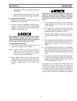
Before making electrical input connections to the
welding machine, “Machinery Lockout Procedures”
should be employed. If the connections are to be
made from a line disconnect switch, the switch
should be padlocked in the off position. If the con-
nection is made from a fusebox, remove the fuses
from the box and padlock the cover in the closed
position. If locking facilities are not available, attach
a red tag to the line disconnect switch (or fuse box)
to warn others that the circuit is being worked on.
2.2.1 INPUT ELECTRICAL REQUIREMENTS
The power source is a single-phase unit and must be
connected to a single-phase power supply. The unit
should be operated on a dedicated circuit to prevent
impairment of performance due to an overloaded circuit.
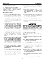
The primary input voltage requirements are noted on the
unit’s rating plate.
2.1 LOCATION
A proper installation site should be selected for the
welding machine, if the unit is to provide dependable
service and remain relatively maintenance free.
A proper installation site permits freedom of air move-
ment into and out of the welding machine, and also least
subjects the unit to dust, dirt, moisture, and corrosive
vapors. A minimum of 18 inches (46 cm) unrestricted
space must be maintained between the welding machine
side and rear panels and the nearest obstruction.
The installation site should also permit easy removal of
the welding machine outer enclosure for maintenance
functions.
CAUTION:
Do not place any filtering device over the
intake air passages of the welding ma-
chine as this would restrict the volume of
intake air and thereby subject the welding
machine internal components to an over-
heating condition and subsequent failure.
Warranty is void if any type of filtering
device is used.
If a forklift vehicle is used for lifting the unit, be sure that
the lift forks are long enough to extend completely under
the base.
2.1.1 LIFTING EYEBOLT
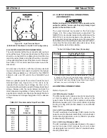
To install lifting eyebolt furnished with the power source,
proceed as follows.
A. Remove the hole plug from the nut in the cover.
B. Install the eyebolt and fully tighten with a suitable
tool.
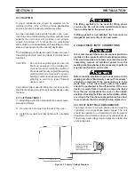
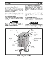
Customers Fused Line
Disconnect Switch
(See Table 2.1 for
recommended fuses)
Figure 2.1 Primary Voltage Diagram


