SECTION 3 OPERATION
11
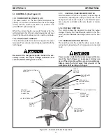
Figure 3.1 - Control and Cable Connections
3.1 CONTROLS (See Figure 3.1)
3.1.1 POWER SWITCH (ON-OFF) (I-O)
The power switch on the front panel energizes the
primary of the main transformer and the low voltage
circuity with the switch in the "ON" ("I") position. The
white READY light will light up.
When the unit overheats or exceeds the duty cycle, the
white light will shut off and output operations will shut
down. The fan will continue to run to cool the unit down.
3.1.2 CONTACTOR CONTROL
The solid state contactor is used to energize the output
terminals. This contactor is controlled on and off with the
torch trigger.
Because of the charged capacitor bank in the sec-
ondary circuit, the output voltage will take a few
seconds before falling to zero volts.
3.1.3
VOLTAGE, PANEL/REMOTE SWITCH
With this switch in the "Panel" position, output voltage is
controlled by adjusting the voltage control knob on the
front panel to the desired output. In the "Remote" posi-
tion, output is controlled at the wire feeder or remote
control.
3.1.4 VOLTAGE CONTROL
This control allows the operator to adjust the output
voltage. Placing the Panel/Remote switch in the "Re-
mote" position disables the voltage control on the front
panel
3.1.5 FEEDER SELECTOR SWITCH
This switch selects the control for either a wire feeder
connected to receptacle J1 or the spool gun connected
to J2.
Power source contactor becomes energized the mo-
ment the torch trigger is depressed. Arcing can
occur if the wire is brought to a ground or workpiece.
Always keep the torch away from ground or the
workpiece until welding is to begin.
POWER
ON/OFF
SWITCH
READY
LIGHT
OUTPUT
VOLTAGE
CONTROL
NEGATIVE
OUTPUT CABLE
CONNECTION
5A CIRCUIT BREAKERS
LOCATION FOR OPTIONAL
METER KIT
SPOOL GUN/
WIRE FEEDER SWITCH
PANEL/REMOTE
SWITCH
3A FUSE
SPOOL GUN CONNECTION
WIRE FEEDER
CONTROL CABLE
CONNECTION
POSITIVE
OUTPUT CABLE
CONNECTION


