EPSON Stylus Pro 10000/10000CF
Revision B
Operating Principles
Printer Mechanism Components
68
CARRIAGE MOVEMENT SECTION
It is the structure that loaded the carriage on the CR guide rail of the aluminum extrusion
corner pipe through the four bearings. Because the rail made of the steel is attached to the
contact/travelling face of the bearing, the friction and vibration of the movement direction
are reduced and durability have improved.
The CR encoder that was attached the slit of the T fence (scale 180a), that is using the direct
current motor for the CR motor and was attached to the CR guide rail in parallel to the
carriage reads and be doing feedback speed control in comparison with the theory control
value on (a linear encoder system), this signal the C362DRV board control circuit. High
printing precision is being maintained by this control.
The drive transmission from the CR motor to carriage is using the steel belt that
maintenance is easy and have endurance.
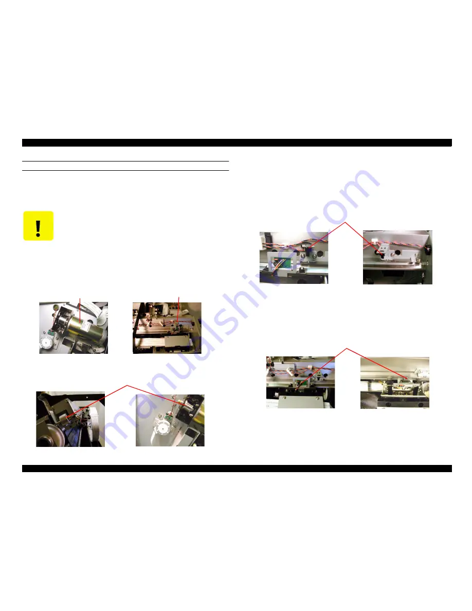
The explanation of the sensor that is used in carriage migration department is as follows.
o
CR_HP sensor
The photo-interrupter that is being attached in the CR guide rail right edge, The flag
(the protrusion) that was mounted to the carriage is detected as the carriage movement
home position (HP). The output from this sensor is ’off’ when the carriage is in the HP
range,’on’ in the HP range outside .
o
CR encoder
It is attached to the carriage surface, and using the pulse output (2 of channel digital)
corresponding to the slit location of the T fence (scale 180a) the top that was
incorporated on the CR guide rail to the servo control and also PTS (Print Timing
Signal) the generation of the CR motor. Resolution is 1/180” in mechanically (the
resolution is 1/720” in software.).
C A U T I O N
n
Do not remove and also loosen the screws fixing the CR guide
rail.
n
Do not do the removal of the carriage. These are the adjustment/
assembly of the order is carried out 1/100mm in the factory.
CR motor
CR encoder
Steel belt
CR_HP sensor
CR encoder
Содержание Stylus Pro 10000 Series
Страница 7: ...Revision Status ...
Страница 8: ...Revision Issued Date Description Rev A March 30 2001 First Release ...
Страница 13: ...C H A P T E R PRODUCTDESCRIPTION ...
Страница 59: ...EPSON Stylus Pro 10000 10000CF Revision B Product Description Jumper Settings 59 ...
Страница 60: ...C H A P T E R OPERATINGPRINCIPLES ...
Страница 86: ...C H A P T E R TROUBLESHOOTING ...
Страница 113: ...C H A P T E R DISASSEMBLY ASSEMBLY ...
Страница 187: ...C H A P T E R ADJUSTMENT ...
Страница 256: ...EPSON Stylus Pro 10000 10000CF Revision B Adjustment Self Diagnostics 256 Following table showing the items ...
Страница 276: ...C H A P T E R MAINTENANCE ...
Страница 289: ...C H A P T E R APPENDIX ...
Страница 302: ...INK SYSTEM ASSY 451 PM10 MC10 EPSON STYLUS PRO 10000 10000CF No 6 Rev 01 10282 456 455 454 453 452 457 ...
Страница 307: ...PM10 MC10 EPSON STYLUS PRO 10000 10000CF No 11 Rev 01 10282 SPINDLE ASSY 902 901 195 902 901 196 ...
Страница 309: ...EPSON Stylus Pro 10000 10000CF Revision A Appendix Component Layout 309 Figure 7 3 C362SUB Board Component Layout ...
Страница 311: ...EPSON Stylus Pro 10000 10000CF Revision A Appendix Component Layout 311 Figure 7 6 C362DRV Board Component Layout 1 2 ...
Страница 312: ...EPSON Stylus Pro 10000 10000CF Revision A Appendix Component Layout 312 Figure 7 7 C362DRV Board Component Layout 2 2 ...
Страница 315: ......
Страница 316: ......
Страница 317: ......
Страница 318: ......
Страница 319: ......
Страница 320: ......
Страница 321: ......
Страница 322: ......
Страница 323: ......


