EPSON Stylus Pro 10000/10000CF
Revision B
Operating Principles
Printer Mechanism Components
70
PLATEN GAP ADJUSTMENT SECTION
the carriage (=head) mounting location always needs to keep regular distance to the space
for printing precision maintenance.
In this printer, as the gap between the form printing face and also head nozzle face become
regular according to paper thickness, the print head nozzle face is variable structure.
The sub carriage that fixed the print head on the carriage that makes the carriage 2 body
structure and become a base is being installed. For the sub carriage moves it in vertical
direction to the space. The cam is used to this mobile system. From the home location of
cam (=PG), for sub carriage to space period changes into linear. When the carriage is in HP
location (the right edge) the gear that was attached on the PG motor and sub carriage drives
the cam, motor revolution (reverse) and cause the sub carriage positioned to specified gap
location.
Doing the paper thickness that is used to 3 stages of the PG small (1.3 mm)/the middle (2.2
mm)/large (2.7 mm) the class division, to keep the distance between the print head nozzle
face and form regularly.
Ink viscosity receives the influence to temperature. The thermistor for temperature
detection is built to each print head, to control ink protrusion speed/protrusion quantity to
same even if temperature changes.
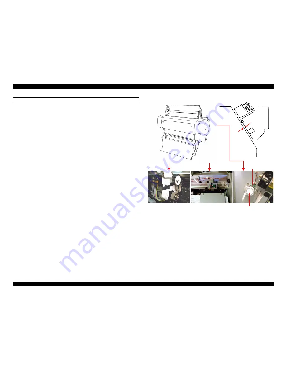
Figure 2-4. Carriage device department-PG adjustment department
The explanation of the sensor that is used in platen gap adjustment department is as follows.
o
HD_SLID (head gap starting point detection) sensor
The mechanical origin (the home) the location detection at the time of modification
actuation for the sub carriage location (the head height from the space) on the carriage.
Being using the reflection style photograph sensor that was attached to I/S frame the
hole location of the gear that was attached on the sub carriage is being detected. When
sensor output is becoming the constitution that becomes "off" (Less than 2.0V) with
the location that the sub carriage dropped most and be actuated detection, sensor output
that the head lowers from the location that rose upward makes the point that changed to
"on" (Over 3.0V) from "off" the mechanical origin and recognize.
CR
guide
rail
HD_SLID sensor
Slide motor
Содержание Stylus Pro 10000 Series
Страница 7: ...Revision Status ...
Страница 8: ...Revision Issued Date Description Rev A March 30 2001 First Release ...
Страница 13: ...C H A P T E R PRODUCTDESCRIPTION ...
Страница 59: ...EPSON Stylus Pro 10000 10000CF Revision B Product Description Jumper Settings 59 ...
Страница 60: ...C H A P T E R OPERATINGPRINCIPLES ...
Страница 86: ...C H A P T E R TROUBLESHOOTING ...
Страница 113: ...C H A P T E R DISASSEMBLY ASSEMBLY ...
Страница 187: ...C H A P T E R ADJUSTMENT ...
Страница 256: ...EPSON Stylus Pro 10000 10000CF Revision B Adjustment Self Diagnostics 256 Following table showing the items ...
Страница 276: ...C H A P T E R MAINTENANCE ...
Страница 289: ...C H A P T E R APPENDIX ...
Страница 302: ...INK SYSTEM ASSY 451 PM10 MC10 EPSON STYLUS PRO 10000 10000CF No 6 Rev 01 10282 456 455 454 453 452 457 ...
Страница 307: ...PM10 MC10 EPSON STYLUS PRO 10000 10000CF No 11 Rev 01 10282 SPINDLE ASSY 902 901 195 902 901 196 ...
Страница 309: ...EPSON Stylus Pro 10000 10000CF Revision A Appendix Component Layout 309 Figure 7 3 C362SUB Board Component Layout ...
Страница 311: ...EPSON Stylus Pro 10000 10000CF Revision A Appendix Component Layout 311 Figure 7 6 C362DRV Board Component Layout 1 2 ...
Страница 312: ...EPSON Stylus Pro 10000 10000CF Revision A Appendix Component Layout 312 Figure 7 7 C362DRV Board Component Layout 2 2 ...
Страница 315: ......
Страница 316: ......
Страница 317: ......
Страница 318: ......
Страница 319: ......
Страница 320: ......
Страница 321: ......
Страница 322: ......
Страница 323: ......


