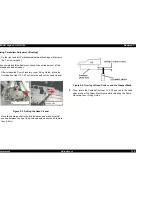
EPSON Stylus COLOR 760
Revision C
Adjustment
Adjustment
116
1.
Fasten the PF motor fixing screw and the No.5 screw securing the
PF motor with 6kg-cm torque once again.
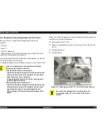
Figure 5-6. PF motor fixing screw & No.1 Screw
2.
Loosen the No.5 screw securing the PF motor a little and engaged
the teethes of the PF motor pinion gear carefully to the teethes of
the Gear 76.
3.
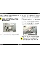
Push the following figured “A” point on the Gear 76 to the Left frame
side. The Gear 76 should be pushed to the Left frame side about
3mm. In case the “A” portion returns to the normal position with the
jarring sounds, the backlash value will be around the Standard
(0.1mm)
But, the following condition is confirmed, the backlash value will not
be suitable.
- The “A” portion of the Gear 76 dose not return to the normal
position. The backlash value is too narrow.
- The “A” portion of the Gear 76 returns to the normal position
without any jarring sounds. The backlash value is too wide.
Figure 5-7. Pushing the Gear 76 to the Left side frame side
C A U T I O N
Do not secure the PF fixing screw and the No.5 screw
with over securing torque. In case the securing torque
is over 6kg-cm, the PF motor may be broken or paper
feed accuracy is lowered.
PF fixing Screw
No.5 Screw
C A U T I O N
When you push the above red circled point by hand,
push the Gear 76 on the Loop scale carefully.
For the another method, turn over the loop scale
carefully around the red circled point and push the
Gear 76 directly.
A
B
C
Pinion Gear PF
Gear 76
Содержание Stylus Color 760
Страница 1: ...EPSONStylusCOLOR760 Color ink jet printer SEIJ99004 SERVICE MANUAL ...
Страница 8: ...C H A P T E R PRODUCTDESCRIPTION ...
Страница 27: ...C H A P T E R OPERATINGPRINCIPLES ...
Страница 53: ...C H A P T E R TROUBLESHOOTING ...
Страница 72: ...C H A P T E R DISASSEMBLYANDASSEMBLY ...
Страница 109: ...C H A P T E R ADJUSTMENT ...
Страница 142: ...C H A P T E R MAINTENANCE ...
Страница 152: ...APPENDIX C H A P T E R ...
Страница 163: ...PSON Stylus COLOR 760 Revision C ppendix Circuit Board Component Layouts 163 Figure 7 5 C298PNL Component Layout ...


