EPSON Stylus COLOR 760
Revision C
Operating Principles
Electrical Circuit Operating Principles
47
2.2.2.3 CR Motor Driver Circuit
The Stylus COLOR 760 is equipped with a DC motor for the CR motor. In
addition to the CPU and ASIC, a slave CPU is mounted on the C298MAIN
board. Since the slave CPU is exclusively used to control DC motors, it
reduces duty of CPU and ASIC to offer faster data processing.
o
CR motor driver circuit
The internal equivalent circuit of the CR motor driver IC (LB1947) is as
shown below.
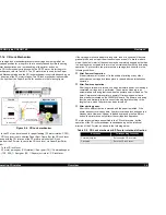
Figure 2-20. Internal Equivalent Circuit of the CR Motor Driver IC
The IC15 slave CPU controls the CR position by referring to the pulses sent
from the linear encoder via IC8 ASIC. The CPU also sets an appropriate
drive current value for the CR position and the direction in which the CR
moves based on the data transmitted from the ASIC. So the slave CPU
outputs specified control signals to the motor driver. The motor driver IC18
then outputs the CR motor drive current to the CR motor based on the
signals sent from the IC15 slave CPU.
Unlike a stepping motor, the DC motor that drives the carriage can not detect
the current carriage position by referring to the pulses given. For this
reason, a linear scale is attached along the carriage operation range to
detect the carriage position. The linear encoder sensor outputs two
kinds of TTL level pulses Phase A and Phase B to IC8 ASIC.
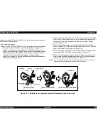
Figure 2-21. CR Linear Scale Encoder Pulse
Direction for the current CR’s movement is detected based on the waveforms
of the Phase A and Phase B that are out of phase, while carriage position is
controlled by using the waveforms output from Phase A on a cycle basis (1
cycle: 1/180 inches). Phase between the output waveforms A and B is as
shown in Figure 2-21. Note all edges in Phase A, Phase B output waveforms
(1/720-inch cycle) are used to control the CR position while it is in the home
position for ink system.
I C 1 8
L B 1 9 4 7
I C 1 5
C 9 0 A 1 3 C A
I C 8
E 0 5 B 7 0 C D
C R - A
C R - B
O U T A
O U T B
-
N M I
N M I
P 3 1
R X D 1
P 3 3
T X D 1
P 3 2
C R B I 3
P 3 0
C R P H A B
P 6 4
C R E N B B
R E S
C R A I 2
M D 2
P 2 5
C P U
C R B I 3
C R A I 0
E N A
E N B
C R A I 1
C R
E
G N D
R 1 1 5
6 8 B K
R 1 1 4
1 2 . 7 K
C 1 1 7
1 5 0 0 p
R 1 1 2
0 . 4 9 9
C 1 1 5
0 . 1 U
+ 5 V
+ 4 2 V
V B B
I N 1
I N 2
S T
V I
M D
P E 1
P E 2
P E 0
P E 4
P A 0
V R E F
+
-
I C 2 4
M 6 2 5 5 2 F P
R 1 3 8
4 . 4 B K
R 1 3 9
4 . 9 9 B K
D A 1
P 1 2
P 2 6
P 1 1
P 1 3
P 2 7
C R B I 2
C N 8
H e a d F F C
A
A
B
B
+
-
+
-
P h o t o
D i o d e s
C o m p a r a t o r s
L E N S
L E D
P h a s e A
P h a s e B
P h a s e A
P h a s e B
P h a s e A
P h a s e B
1/720 inches
1/180 inches
1/360 inches
CR Motor CW rotation
CR motor CCW rotation
Содержание Stylus Color 760
Страница 1: ...EPSONStylusCOLOR760 Color ink jet printer SEIJ99004 SERVICE MANUAL ...
Страница 8: ...C H A P T E R PRODUCTDESCRIPTION ...
Страница 27: ...C H A P T E R OPERATINGPRINCIPLES ...
Страница 53: ...C H A P T E R TROUBLESHOOTING ...
Страница 72: ...C H A P T E R DISASSEMBLYANDASSEMBLY ...
Страница 109: ...C H A P T E R ADJUSTMENT ...
Страница 142: ...C H A P T E R MAINTENANCE ...
Страница 152: ...APPENDIX C H A P T E R ...
Страница 163: ...PSON Stylus COLOR 760 Revision C ppendix Circuit Board Component Layouts 163 Figure 7 5 C298PNL Component Layout ...


